Tuesday, August 25, 2015

Construction - AGS System for Passive Solar Heating and Air Conditioning - Cont'd Lots More

This is the third post on the design and installation of the AGS system.  Since our iteration of the solar collector is one-of-a-kind, this post runs long in order to hit all of what I consider to be the important details, including some mistakes.  

The first post detailed the conduits that carry the heat from the summer sun to the thermal mass under and around the house.  The second post focused on size of the solar collector and the excavations necessary to build it into the slope in front of the house.  This post deals mostly with the construction of the shell for the collector, connecting the conduits to the collector and closing up the excavation. (Click on any photo to enlarge it..)

Walls
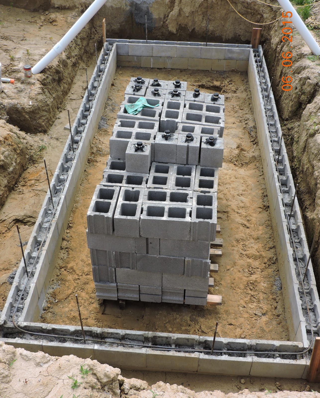
Since the collector is buried in the ground, the walls have to brace several feet of backfill. It could have been constructed with poured concrete on a poured footing resting on virgin soil, similar to a foundation wall.  In order to save money and to be able to design it as we went, I opted for dry-stacked concrete blocks resting on virgin soil and sand.  The first course
Bond beam course partially filled; horizontal rebar in place
was 4" x 8" x 16" partition concrete blocks  in order to have a smooth surface against the ground. The north wall was 12 courses high (about 8') -- one course higher than the final grade. The south wall could be 4 courses shorter than the north wall due to the slope of the hillside. The ends were stepped to reconcile the differences in height of the north and south walls. The walls were then capped with 2 x 10 pressure treated boards bedded in mortar and fastened with anchor bolts.  


The collector will need a fence to meet code.  The decision between mounting it on the top of the walls or setting it back a ways so as not to shade the collector will be made eventually after observing the solar gain on the finished collector. The fence will also have to be designed to keep small non-climbing critters out.  As far as deer are concerned, all we can do is pray that one doesn't jump in and land on the glass.
Friend Dave covering the rebar with more concrete; the
ramp above him was used to slide buckets of concrete
and cinder blocks into the pit.  The sprayer was used to.
moisten the blocks before adding concrete.

The tall north wall was reinforced horizontally with three courses of bond beam blocks filled with concrete and #4 re-bar -- one bond beam course near the bottom, another halfway up and the other near the top. The other three walls, since they were shorter, had only two bond beam courses. The cores of the corner blocks and the cores of about a half of the intervening blocks for all four walls were filled vertically with concrete, except, as explained below, the south wall had fewer unfilled cores.

Extending about a foot downward into the soil from the bottom of vertically-filled cores in all four walls were 3" Schedule 40 PVC pipes that were filled with concrete when the cores above them were filled.  They also held the lower end of the vertical re-bars that rested on 2" PVC pipe caps dropped into the 3" pipes upside down. The purpose of the caps was to keep the rebar from coming in contact with the soil to eliminate the problem with the steel rusting, expanding and cracking the concrete. The purpose of the 3" PVC extensions, well anchored in undisturbed soil, was to resist the lateral pressure of the backfill against the bottom of the wall.

Fiber Bonded Cement Parge
Both sides of the walls were parged (stuccoed) with fiber-bonded cement as is typical with dry-stacked cinder blocks, except for the south wall where there was not
Half blocks were turned on edge to provide entry holes
for the smooth conduits; other half blocks in all four walls
 contain pre-made weep holes ; the picture was made
 just before the top row of bond beam blocks and many of
 the cores were filled with concrete and rebar.
enough room between the blocks and the excavation in which to work.  To compensate for the lack of parging on the outside of this wall (the compression side of the wall) additional cores were filled vertically with concrete. I can live with this compromise because it is the shortest wall and, for strength of a dry-stacked wall, it is more important to parge the tension side. Parging of at least 1/16th of an inch thick on the compression side and 1/8th on the tension side in tandem with selective core-filling gives a much stronger wall than the typical mortared block wall -- actually strength that more nearly matches a monolithic concrete wall (Rob Roy, "Earth-
Closeup of a weep hole pre-made from a half block
 turned on edge; PVC pipe was concreted in and
 geo-textile fabric was added prior to dry stacking
Sheltered Houses", New Society Publishers, 2006, p.102).  The other three walls were parged on both sides which, in addition to strengthening them, also eliminates water penetration through the (un-mortared) gaps between blocks.


The integrity of the taller north wall was severely tested only a week or so after backfilling (without compaction) when, not one but two, concrete trucks parked on the backfill while pouring the footing for the north wall of the house. After the trucks left, the backfill was thoroughly compacted -- it had sunken by a foot and a half.

Weather Related Change
Unfortunately, heavy rains over a period of several weeks (global warming induced?) not only delayed construction but created more work.  The rains started after three courses of blocks were stacked. The run-off followed the gravel around the conduits from the huge area that was graded for the slab floor directly into the "pit" to deposit 8 - 12" of  silt in the
Two concrete trucks parked on the backfill for the collector
with no ill-effects on the DIY walls of the collector.  (Whew!)
over-dig surrounding the walls of the collector and on the floor inside the walls. This circumstance was a mixed blessing.  On the one hand, how better to get compacted backfill around the base of the wall? But, on the other hand, the parging could not be carried as far down on the wall as intended. Consequently, we filled with concrete all of the cores in the first course of conventional blocks as well as the first bond beam course. This change should more than compensate for not being able to start the parging at the bottom of the wall.


Managing the Water Problem During Construction and Beyond
It is a given that the collector, being in a pit, will collect water as well as sunlight.  A good thing happened unexpectedly during the excavation that solved the water problem. The excavation for the collector was deep enough to uncover near its center one of the French drains but, unfortunately, beyond where it had been perforated (details on perforation).  So I removed a 5' section of the exposed drain and substituted a new section that was copiously perforated and wrapped with the same geo-textile fabric used with the French drains originally.  The replacement was sorely tested during numerous hard rains in May and continuing through early August because, as mentioned above, most of the runoff from the house footprint followed the conduits into the excavation for the collector. After a rain, the house footprint dried out within three or four days but the pit not for a week or so.   However, without the serendipitous drain, water would have stood in the pit indefinitely because our wind-blown loess does not naturally drain as quickly as loamier soils.  

The record rainfall in June was slightly more than three times that of normal.  To eliminate some of the runoff that had been so readily finding the collector, I finally resorted to covering the footprint of the house
The house footprint, except for garage, was covered with
tarps; the soil, conduits and gravel behind house were
 covered with plastic
with huge tarps that I had found on Craigslist well in advance of starting construction, knowing that they would be useful in some manner later. Then, just before the remnants of tropical storm Bill reached us, I covered the north ends of the AGS conduits and the gravel around them with 6 mil plastic sheeting pinned down with 8" and 12" exterior spikes and further anchored with blocks and unused PVC pipes.  This arrangement kept most of the water on the surface instead of following the conduits into the collector (at least for a few weeks until UV rays caused the plastic to fail but enough time to get the collector finished).  I then hand-dug shallow trenches south of the tarps in order to channel the surface water away from the excavation. The system was immediately tested with 4" of rain in three days whereby the amount of water reaching the pit was limited and quickly siphoned away by the French drain. Such a trial run would seem to indicate that the serendipitous drain will keep the collector sufficiently dry in the future.

The ends of some of the corrugated pipes are visible while 
others are hidden by collapsed soil and gravel that was
undermined by runoff  following the conduit trenches.

Between now and when the time is right to finish the collector, presumably in about a year, the extra dirt that the water has deposited on the floor will have to be removed, the floor sloped towards the French drain and a few inches of white gravel added with landscaping fabric underneath.   Once the excavation for the conduits and the space around the collector have been backfilled, the slab floor for the house has been poured and the insulation/watershed umbrella has been installed, the only water inside the collector will be limited to whatever falls into the collector itself and should be easily handled by the French drain. 
Pat attaches a fitting to connect the last (of nine) corrugated
conduits to a Schedule 40 pipe running to the collector.
 Keith prepares the sand bed for the horizontal insulation under
 the pipe.  Two of the four pier forms have been installed over
 pre-poured footings and the vertical insulation is in place along
the west wall of the excavation.  The sand was subsequently
reconfigured to to cover the pipes uniformly to a depth of
 four inches.

The white gravel for the floor of the collector will be ideal for reflecting short wave length solar radiation and converting it into long wave length that cannot pass back through the glazing (greenhouse effect). The collector will be designed to funnel the resulting heat into the conduits where it will flow passively about 78' to daylight  (20' of smooth pipe between the collector and the house, 38 ' of corrugated pipe under the house and another +/- 20'  of smooth pipe behind the house).

With regard to plant growth inside the collector, the assumption is that, once the collector is finished, the temperature inside will be too hot for plant growth.  The use of landscaping fabric under the gravel may therefore be unnecessary, at least for the hottest part of the summer.  But maybe we will have created the perfect greenhouse and plants will be a big problem despite the fabric, in which case, more drastic and unwelcomed measures will be necessary -- only time will tell.

Foundation Footings over the AGS Conduits
Parging the south wall with fiber bonded cement.  Notice
the anchor bolts for the 2 x 10 pressure treated boards
 that will cap the top of the wall.
In hindsight, we should have trenched for the corrugated pipes well beyond the south wall of the house so that the footings and foundation wall would be resting on virgin soil.  As it was, the excavation that was necessary to uncover the corrugated pipes so they could be joined with the smooth conduits severely undermined the footings, foundation wall and the edge of the slab floor.  To make matters worse, rains caused soil and gravel around the pipes to collapse into the excavation (check out the sixth pic from the top).  As referenced in the second post, four concrete piers about 5 - 6' apart were inserted between conduits to support the footings and wall then the excavation around the piers, under the slab and for a ways in front of the house was backfilled with rock that was dropped from sufficient height to be 95% compacted. That part of the footing for the south wall of the house bridging across the excavation will be beefed up vertically with twice the amount of concrete and rebar since it is basically a beam supported by the rock and piers.

Insulation
In conjunction with installing the PVC pipes that bridge between the corrugated pipes and the collector, four sides of the excavation were insulated -- the floor, the north wall of the collector and the east and west walls.   One layer of two-inch thick extruded polyethylene insulation board was laid on the floor of the excavation over a thin layer of sand.   I considered using expanded polyethylene (Styrofoam) for a couple of reasons but opted for extruded with its 250 psi compressive strength since there will be 5 - 6' of backfill on top with vehicular traffic passing over during construction. The sides of the excavation were also insulated as was the outside of the north wall of the collector but, since these areas did not have to carry heavy loads, cheaper 150 psi was used..  Actually, the insulation for the north wall of the collector was mostly a freebie from the local farm and home store.  It was Styrofoam in big chunks that were easily carved up with table and handsaws. 

I decided to use extruded polyethylene for insulation with some trepidation after having run onto a YouTube posting showing water being rung from extruded poly which contradicts the claim of extruded polyethylene as to its low water absorption. (Water logging reduces R-value to near zero.)  Expanded poly is used universally in wet environments from insulated concrete forms to boat docks, so maybe it makes sense to use it subgrade and devise ways of protecting it from loading.  More on this subject in a subsequent post on the AGS insulation/watershed umbrella.

The primary reason for insulating the excavation at all is to prevent heat loss from the conduits to the soil in front of the house before it can reach the thermal mass under the
Backfilling with rock around the piers to help support the
footings under the front wall of the house.
house.  A secondary reason is
 to reduce heat loss from under the house when the AGS system mothballs for winter.  The insulation of the conduits will be complete when the insulation-watershed umbrella is installed below grade a couple of feet above the pipes.  If water saturation is indeed a problem with the extruded poly insulation, the umbrella should keep it dry enough to function anyhow.

Backfilling
Backfilling of the excavation was done in stages as soon as the collector walls were built, the rigid conduits were connected to the corrugated conduits and bedded in in sand, the insulation
Completing the backfill of the excavation over the AGS
conduits that were bedded in sand ahead of time.
was in place and the footings for the piers as well as the piers themselves were poured. Sand was used first to support the rigid pipes and cover them to a depth of about 4" to protect them from the rock and soil falling from the backhoe.  


First, clean rock was dropped in to provide a more compacted base for the footings, foundation wall and slab floor.   The rest of the excavation was filled with uncompacted dirt which should be sufficiently settled by the time the insulation/watershed umbrella is installed.


Air Flow
Presumably, we will be ready by next summer to finish the collector which will include building the framework to support  the glass. The south side of the framework, 18" in from the south wall, will comprise mostly air vents because the cross-sectional area of the vents will need to be considerably more than that of the cross-sectional area of the nine AGS conduits added together in order to be absolutely sure air flow through the conduits is not impeded by a lack of intake air. And the vents will require something like hardware cloth to keep critters out of the collector and conduits.

Monday, August 3, 2015

Odds 'N Ends - Lesson from a Tepee (Cont'd)

The first post on tepees covered many of their unique features such as shape, orientation, materials, smoke flap function, insect control and some of the Youngs' camping experiences in a tepee, including winter camping.  This post adds other interesting tepee factoids.

Tepee Poles
The plains Indians lived nowhere near good trees for poles and had to travel several
Lodgepole pines
hundred miles west to the Rockies to harvest lodgepole pines.  Consequently, poles were
cherished and lasted a long time.  The 14 poles supporting the cover were traditionally several feet taller than the cover while the two poles that moved the smoke flaps were shorter. Two of the oldest and most dispensable poles were used for the travois which meant that dragging them on the ground behind a horse wore them shorter.  So they were relegated to smoke flap poles.  I suspect the extra length for the other poles was intended to delay pole-cutting treks to the mountains as long as possible.  As the bottoms of the poles deteriorated from being in contact with the ground, the extra length allowed the poles to be shortened many times before having to be demoted to smoke flap duty or replaced entirely.

For a 20' tall tepee like those we had, the poles needed to be at least 24' long.  The unique thing about a long lodgepole is that the diameter at the tip is only slightly smaller than the diameter at the base -- only about 2 - 3" for tepees.  The minimal taper gives them the stiffness they need to carry the weight of the canvas despite being so slender.

Pitching the Tepee
If the squaws were responsible for pitching and striking the tepees, ever wonder how agile some of them must have been to shinny up the poles to tie and untie them at the top?  Didn't happen.  The three sturdiest poles are tied together flat on the ground then spread out and tilted into place to form a tripod.  The excess rope dangling from the top is more than long enough to touch the ground.   The other 11 poles are then laid into the forks of the first three in a very precise order.  After the poles are in place, the excess rope is wrapped from the ground around all of the poles and tied off to one of the tripod poles.

The cover is raised and secured just as easily.  It is laid on the ground around the periphery of the tepee with its midpoint directly opposite where the door will be.  Then the smoke flap poles are inserted into the pockets for them at the top of the smoke flaps and used to lift the cover into place.  It is subsequently draped around the poles towards the door then overlapped over the door and laced together with 1/4" thick sticks that fit in matching pairs of "button holes".  The nearest thing to climbing the squaws might have had to do was to secure a stick across the door opening on which to stand while lacing the cover together.

Doesn't It Rain In Around the Poles?
Yes, but not much. Most of the water runs down the underneath side of the poles to the ground unimpeded as long as the poles are smooth and there are no obstructions.  Consequently, the poles have to be debarked while they are green and the knots that are left where the limbs were have to be shaved smooth.  Moreover, the ropes that attach the liner to the poles cannot lie directly against the poles.  Instead, two small twigs are wedged under the rope to hold it away from the pole on the underneath side, providing a clear waterway to the ground.

As mentioned in a prior post, our first tepee was pitched in Illinois in the mid-70's.  Rather than having 16 lodgepole pine poles shipped from one of  the Rocky Mountain states, we used native trees with terrible results.  They were bulky, heavy, crooked, tapered too much and were difficult to get smooth enough to carry the water to the ground without drips.  We ended up shortening the poles to just above the liner and covering them with a god-awful metal lid from a hog feeder.  Ugly and insulting to tepee-ism.

After a couple of years of making do, we took the tepee to Colorado for a two-week camping vacation.  We arranged a head of time to pick up new lodgepoles near Aspen (which gave us an opportunity to tour the town overnight).  We then hauled the poles on the rack atop of our DIY trailer behind our 4-W drive International Scout to Crested Butte, a ski town that was the nearest civilization to our planned campsite at 11,000 feet. Interestingly, Aspen and Crested Butte are hiking distance apart as the crow flies but multiple hours apart by road because they are separated by the continental divide. One of the ski resort motels in Crested Butte stayed open during the summer so we touristed Crested Butte by evening and de-knotted our tepee poles with butcher knives on the motel parking lot by day.

Eventually, we did have a second set of poles shipped from Montana when the original set deteriorated after about 15 years.  The truck driver was amused by a bundle of "What?" that was more than half as long as his trailer.  As mentioned in a prior post, we took the cover home during the summer but we left the poles in place and unprotected.  Otherwise, a second set would not have been necessary

Isn't the Tepee Smokey?
Also as explained in detail in a prior post, the smoke from the campfire is at the mercy of wind direction and barometric pressure.  The relationship between the liner and the cover in conjunction with the smoke flaps limit the amount of smoke campers have to deal with -- much less actually than around a campfire in the open -- because the fire inside is controlled and predictable.  

There is no wind inside, so the heat of the fire causes the smoke to rise naturally whereby the air coming in between the liner and the cover picks it up and carries it out through the smoke flaps.  Make-up air for the fire enters in an intentional manner either below the door or through an opening around the door that is tailored in size to the amount of air needed for the fire -- much like opening and closing a stove damper.  

Okay, What Is the Lesson That the Tepee Teaches Us?
For some it may be a stretch but for me it is easy to see a parallel between the tepee and green building to the degree that both work with nature instead of against her. In my view, that characteristic goes a long way in defining sustainability.