Saturday, August 20, 2016

Construction - Carpentery Phase Begins with Interior Bearing Walls

Now that most of the dirt and concrete work are behind us, the carpentry work can begin in earnest.  However, some "infrastructure" work needed to be done first.

"Infrastructure" First
The carpentry phase of the project will take quite a while since I will be working alone most of the time and working alone is several multiples slower than twice the time of two workers or three times the time of three workers.  So, it makes sense for me to acknowledge the situation and spend as much time as necessary upfront to shorten and simplify the process downstream.  

Consequently, I used a couple of substantial steel desks that I "inherited" to create a sawing station.  I secured the compound miter saw to them well enough that stealing it would be too much trouble. By covering it with a tote to protect it from the weather, it can be left in place indefinitely.  I created a way to lock the abundance of the drawers in the desks in one fell swoop so as to be able to store tools and supplies on site.  Instead of installing temporary electric service and incurring a minimum per-month-charge for a meter, I ran a 10 ga extension cord from my workshop next door high enough overhead to be safe from tall vehicles.  I made provisions for locking the ladders under a cover.  And, as will be discussed below, I spent lots of time simply building a safe scaffold that will stay in place until after the drywall that can be reached from it is hung, taped and painted.

Sequencing Wall Construction
A must read for anyone doing construction alone
I made the decision to reverse the order of wall construction over what a professional builder would likely do, viz., I am building the interior bearing walls ahead of the exterior walls. The exterior walls will be constructed from shop-built  wall trusses and window-housing wall sections that have plywood and OSB elements that would not survive prolonged exposure to wet weather. Consequently, they will need to be roofed over as soon as possible after being raised. By contrast, the interior bearing walls will have no plywood or OSB so will be more able to handle some rain while I raise the exterior walls and construct the roof. Accordingly, I began with the most interior of the interior walls -- a tall wall that parallels the north concrete wall -- and, in conjunction with it, the scaffold.  It is mid-August and we are entering what is usually a drier season.  I am hoping to erect the exterior walls and get the roof in place before the Spring rains start.

The Long and Tall Bearing Wall
The first wall is 56' long, 16' tall and parallels and stands 5' away from the north concrete wall.  Eventually, it will divide the living space from the storage area (see the architectural drawings).  Four of us raised it in three sections that I tied togetherlater via 2 x 12 headers and, for a short section, the second component of a double top plate.  The fourth section (last photo below) was added subsequently with the help of volunteers.

Since the wall is so tall, scaffolding was necessary early on for joining the wall sections with a top plate or headers. The scaffolding will also be necessary later for adding a short truss wall to the top of the concrete wall and for setting the roof rafters.  And, as mentioned above, It will stay in place until the dry-walling and painting above it are done.  I suspended the scaffold between the two walls flush with the top of the 12' concrete wall. Not only does it serve as a work surface, it also holds the tall wall plumb until it can be tied to the roof.  As you can see in the pictures, the scaffold framing is all salvaged lumber and the plywood deck has been weatherized with stain so it can be reused later.
Above left photo:  interior view of scaffold.  Right photo:  exterior
view of scaffold; notice stationary ladder and the rope from the 
pulley hanging from the guard rail that runs to a box below
 for raising tools and supplies to the scaffold

It takes only a glance at the wall framing to appreciate the challenge of installing the three double 2 x 12 headers after the wall was raised while working alone, especially the one at the 16' height. I was able to do it primarily from reading John Carroll's "Working Alone". His individual methods come in handy but its major impact is the way it fosters a different way of looking at construction that makes the seemingly impossible quite possible.  It would have been a real challenge to have assembled the headers on the floor then attempt to raise them by myself. So I raised the pieces for each header separately, which in itself was a bit of a challenge for the higher headers, and assembled them in place -- without Carroll's influence I probably would have been calling for volunteers and waiting until they were free.

The long low header to the right in the photo below bridges over the numerous stubbed-out ends of the PEX water supply lines that run separately to each faucet in the kitchen, bath and laundry (home-run configuration).  They emerge from the concrete just barely behind the wall but the temporary bracing that holds them in place now would interfere with raising the wall in front of them.  The header allows me to postpone piecing together the bottom of the wall until the bracing is removed.

Salvaged Lumber Situation

As you can tell by the color of the lumber in the tall wall, most is new.  There were not many salvaged 2 x 4s long enough and straight enough for the job.  Pre-building the wall trusses over the past couple of winters consumed most of the salvaged 2 x 4s that were in the eight-foot range and the section of the tall wall being installed in the photo below used the few that were longer.  My current inventory of salvaged 2 x 4s is mostly boards that are less than 8' but will work or can be made to work, for most of the other interior walls. Ultimately, I do not expect to have to buy many new studs.  As for the 2 x 6 walls, there will be enough salvage for all of them.
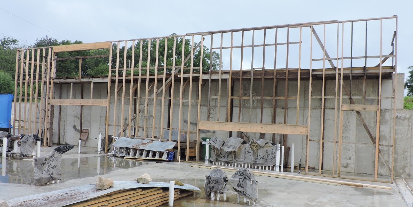
Frontal view of the wall after the section being raised in the next photo is in place;
the headers to the left are in association with a second story room that protrudes
 through the wall; the header to the right bridges across the termination of a 
dozen or more PEX water supply lines
(as with all the photos, clicking on the pic will enlarge it for better viewing)
Design of the Tall Wall
Initially after raising the wall, there were two large openings above substantial headers. As can be seen in the fourth photo, the opening to the left is to accomodate a second story balcony-like office that will cantilever through and extend 2' beyond the tall wall. Before the the photo was taken, the other opening to the right of the wall above the header that is just over the PEX plumbing rough-ins (under the burlap). The fifth photo shows the fourth and last section going in over the 
The fourth section goes up with two of us pulling from  the scaffold
plumbing with the help of friends and family.  

The Next Line of Bearing Walls
Actually, the next line of east-west "bearing walls" that are slated for the middle of the house, comprise as many post-supported beams as stick-built walls due to the open floor plan in the dining room/kitchen/living room area.  These mid-line bearing structures will support  the second story south wall and the catwalk just inside of it but not alone -- the floor framing for two second story rooms plays a role as well.  All this will be covered in the next post.

Friday, August 12, 2016

Design - Final Architectural Drawings


Perspective
I have deliberately withheld the architectural drawings until now (the 84th post to the blog) because most of the dirt work and concrete work, except for that pertaining to the AGS system*, is pretty generic for any slab-on-grade house and the drawings would not have added much value.  The atypical dirt and concrete work for the AGS system*, although definitely unique, was only loosely influenced by the floor plan. But, now that we are ready to start building vertically with wood, the architectural drawings may perhaps be of interest.  

The drawings lack the finite details that are typical of most construction projects. The design is mine so the drawings were mostly a matter of professionalizing my amateur drawings so the structural engineer would stamp them and the Building Director would accept them.  Not only was the Building Director comfortable with letting me sweat the details, he encouraged me not to pay additional architectural fees for more detailed plans. Because we had already had 5+ years of collaboration on the project, he was also willing to trust me to make changes without checking with him first. 

(For a blow-up view of any drawing, click on it or click on the first drawing to blow it up then scroll down through the rest of the drawings.)

Design Summary
The house is nestled into a 15 degree slope so as to have the right amount of earth contact and it faces south so as to benefit from the sun's energy for passive solar heating and air conditioning via a system called Annualized GeoSolar*.  It would qualify as a two-bedroom, two-bath ranch except it has two second-story rooms -- a third bedroom and an office.  As is typical with passive solar homes, the house is longer east and west than north and south -- by a factor of 2:1. It has earth contact with nearly all of the two-story north wall, half of the west wall and with a slab-on-grade floor. All but three small windows face south but, by virtue of clerestory windows, there are no rooms without dedicated windows. The two-car garage is attached and is heated by the same AGS system as the house but to a lesser degree.  The "back door" into the kitchen leads in from the screened porch in front of the house. Except for the second story, the house exceeds compliance criteria for the American Disability Act.  

Page One
Page 1 contains two drawings showing the front and back of the house.  The top drawing
is useful for visualizing the screened porch and garage relative to the house and the abundance of south-facing windows for passive solar gain. This drawing and the one on page 5 shows a photo-voltaic array for generating electricity as well as serving as the overhang for the second story windows. This early idea was abandoned in favor of a site-built overhang and a free-standing, post-mounted array to the north of the house. Otherwise, we are adhering pretty closely to the drawings.

The second drawing shows the extent of backfill against the tall north concrete wall -- almost 12' above floor level in the center.  It also shows a short stick-built wall on top of the concrete.  The abrupt changes in elevation of the backfill represents the location of retaining walls running north.

Page Two
Page 2 shows the details for the footings, foundation, concrete walls and concrete slab. With regard to the tall north wall, the design shown here is not what the structural engineer accepted but what he designed and stamped was not what we did. With the blessing of the Building Director,  we poured a 10" thick wall, instead of 12", and used three deadmen and two right-angle west and east walls to brace it. We also poured a slab at least 5" thick and reinforced with fiberglass fibers instead of a 4" with steel mesh reinforcement as called for in the drawing.  Otherwise, we stayed with the drawing.

Page Three
Page 3 is the floor plan for the lower story. Here we are taking liberty with the drawing in the living space adjacent to the garage. The drawing shows a workshop north of an airlock. When we were able unexpectedly to buy the property next door to the building site and use it as our our temporary residence, I turned its large free-standing garage into a workshop which I will keep even after we convert the temporary residence to rental property. The workshop area in the plans then morphed into more living room space, a reconfigured airlock and more storage area. The DIY picture of the altered floor plan appears as the last photo below with my pencil drawing of the changes taped over the original drawing.  Otherwise, we are sticking to the plan.


Page Four
Page 4 shows the second story layout.  There is a balcony office over the bathrooms that looks out over the living room towards the east but not over the master bedroom on the west. There is an east-west catwalk cantilevered over the living room and master bedroom. Towards the east it connects a bedroom to the stairs and office and towards the west it extends out over the master bedroom. It serves three functions:  (1) it provides access to the second-story bedroom; (2) it provides access to the clearstory windows for opening and closing, washing and, perhaps someday, managing thermal shades and (3) it adds architectural interest. 

Page Five
Page 5 shows primarily the east and west profiles of the house and screened porch as well as a north-south cross-section at the level of the stairway.  

It brings dimension to the extraordinarily high ceilings in the living room and master bedroom -- 20' from the floor at the clerestory windows and 16' at the partition between living quarters and storage area. The high ceilings will allow light from the clerestories to reach the back of the living room and master bedroom. The drawings clearly show no windows on the west, three small ones on the east, two of which are in the garage, and the rest facing south.

Altered Floor Plan (Last Photo)
The workshop has been eliminated and its space reallocated to the living room and some to the storage area along the north wall.  The long dimension of the airlock was shifted 90 degrees for better utilization of the abandoned workshop space for the living room.
____________________

* For information on Annualized GeoSolar, click on the "Featured Post" in the left column above which is the the first of three posts on AGS.

Tuesday, August 2, 2016

Construction - Summary of the Dirt and Concrete Phase of Construction

Reminder:  A click on any photo enlarges it for closer inspection.  Also, for details on the phases of construction discussed below, click on the appropriate links to previous posts.

Broke Ground
We broke ground on August 3, 2014.  It took about a month's worth of track loader digging for me to rough out the excavation into the side of the hill --  a lot of trips up and
Pre-made French drains:  Wrapping perforated culvert
with specialized geo-textile fabric
down the hill to carry the dirt to storage behind and to the side of the building site.  Rain and cold weather pretty much put a stop to the dirt work leading up to and during the winter.  Meanwhile, I used the time away from the dig to fabricate French drains that were of custom design and to begin assembling exterior wall trusses in my workshop.


French Drains and Solar Collector
 Installing AGS conduit after the French drains were backfilled
April of '15 was an unusually dry month for April which allowed a excavation contractor to smooth and grade the footprint for the house. Then, as he dug trenches for the French drains,  a crew of volunteers snaked the long drains to the trenches and lowered them to place with ropes.  Once the trenches were backfilled, the contractor began trenching for the conduits for the AGS system* and dug the pit for the solar collector.  With the help of volunteers, the conduits were installed and backfilled just before a rainy May and early June.  Between frequent rains, I, with occasional help from friends and family, managed to get the solar collector built using dry-stacked concrete blocks parged with fiber-bonded cement. By mid-summer we had the conduits connected to the collector and associated backfilling done. 
Solar collector:  Notice pipes exiting the back wall that connect to the
conduits under the house which, in turn, connect with the pipes
running to daylight behind the house; when the collector is finished,
heat from the summer sun will course through the conduits and warm
the soil under the house; heat from the soil will conduct through the floor
 and the concrete back wall to condition the house in lieu of conventional HVAC


Footings, Concrete Walls and Shallow Frost-Proof Foundation
The concrete work was begun in late summer of '15 and barely completed before freezing
weather.  The contractor dug the trenches for footings to support the north and west concrete walls and
Concrete walls in place; shallow frost-protected foundation poured inside
of insulated concrete forms; waste plumbing roughed-in
 the foundation under the stick-built walls. I did what forming needed to be done for the wide footing for the concrete west and north walls and the contractor poured the footing then poured the wall.  With some help from volunteers, I formed up and poured the narrow footing for the foundation under the stick-built walls.  A friend and
 I erected the insulated concrete forms for the shallow frost-protected foundation over the narrow footing and several of us poured the foundation inside the forms.  All that remained of the concrete work were the floors for the house, garage and screened porch. However, they had to be put on hold until the electrical and plumbing rough-ins, situated below the floor, were done. 

Plumbing and Electrical Rough-Ins; Slab Floor; Partial Backfilling
By mid-October, I had the plumbing and electrical rough-ins ready for slinging the gravel sub-base and pouring the slab floor.  The contractor poured the floor but only for the house
Supply plumbing and electrical rough-ins done; gravel sub-base and
plastic sheeting in place; house slab in process
-- the garage and screened porch were put on hold.  A few weeks later, I damp-proofed the concrete walls and installed a footing French drain at the base of the walls and ran it to daylight in front of the house at both ends. Then I backfilled the north wall to about half its height and sloped the grade behind the house for efficient surface drainage in preparation for upcoming rainy weather and winter freezing.  As recommended by the concrete contractor, I coated the fresh slab with a sealant to prevent damage to the fresh concrete from freezing and covered the exposed footings with 2" EPS (styrofoam) for the same reason.  That was about all we could do towards construction until Spring so I turned my attention to several upgrades to the old farmhouse in which we live next to the building site.  Also I was able to finish building the wall trusses that we will need this summer for the exterior walls and to erect a temporary enclosure in which to store them.


Retaining Wall
West wall of the house insulated and partially parged with
stucco; retaining wall in place with insulation and two layers
of plastic behind and under it as part of the
insulation/watershed umbrella for the AGS system*;
partially backfilled
The first project for the early Spring of 2016, was building a retaining wall running west from the west concrete wall.  However, as part of the umbrella for the AGS system*, I had to insulate the outside of the wall first using a DIY method described in detail in a recent post, as well as insulate the ground on which it would be resting. With the help of many volunteers, a formidable wall went up in about two hours time using foundation stones salvaged from a 19th century barn.  Then, while waiting for the Spring rains to subside, I shop-built the exterior wall sections that will house the windows and stored them on the house slab under cover.

Screened Porch Slab; Garage Slab; Retrofitted Concrete Wall
A lot of June and July was spent on the screened porch and the garage.  I formed up and
Footing, foundation and slab completed for the screened porch
poured the footings and foundation for the screened porch in preparation for the pouring of the porch slab by the concrete contractor.  As part of the umbrella for the AGS system*, I also worked on insulating the porch floor and insulating the garage floor so that the contractor could pour them as well.  I had miscalculated on the design of the east wall of the garage and ended up asking the contractor to add four feet of height to it in conjunction with his pouring of the porch and garage.  I recently spent a couple 
Pouring the garage floor; addition to the east wall of garage already poured
of weeks between rains insulating the new east wall of the garage.
  Also, I added one more layer of backfill to the north wall to bring it up to the top of the previously-installed damp-proofing membrane -- to a depth of about 8' -- (only to learn later through a comment submitted to the blog that I had installed it backwards).


*          *          *          *          *          *          *          *          *          *          *  

In a nutshell, it has taken me two years to be reach the carpentry phase of construction partly because the dirt and concrete phase has been so weather-dependent.  I would guess that it will take another two years to have the house ready for occupancy -- maybe 6 mos to get it under cover and 18 mos to finish it -- but the weather will be inconsequential by comparison since the work will be done on the slab floor and soon under cover. 

There will be more dirt work to do before winter of this year, principally, completing the umbrella for the AGS system* in front of the house, and more to do in back of the house next year but all of the concrete work and most of the dirt work are history.
_________________
* For information on the Annualized GeoSolar system, click on the "Featured Post" in the left column above which is the first of three posts on AGS.