Tuesday, September 27, 2016

Construction - Back to Dirt Work - The Insulation/Watershed Umbrella

As much as I would have liked to have continued with the carpentry phase of construction, the reality was that it was mid-September and we had only a few weeks to finalize the grade in front of the house and get it planted with a cover crop to control erosion during the rainy season next Spring.  Consequently, with the internal bearing walls in place, it was time to shift our attention to more dirt work.

The main job was to get the insulation/waterhed umbrella installed.  (Click on the "Featured Post" feature in the left column for linkage to Annualized GeoSolar and the role of the umbrella.)  However, loose ends had to be taken care of first.  The porch foundation had to be insulated and clad in the manner described for the east garage wall.  The exterior of the insulated concrete forms for the house foundation wall had already been covered with cement board but still had to be parged with stucco.  The grade needed tweeking before the umbrella was installed.  The umbrella needed to be laid down and covered with topsoil and the topsoil needed to be blended with the grade further down the hill in front of the house.  Finally, the cover crop needed to be planted no latter than mid-October.  Oh, boy! The race was on.

Insulation for the porch foundation; the footing extends
below the insulation and will be insulated eventually with
more foam board laid horizontally
Insulating the Porch Foundation
Cement board over the insulation
The foundation for the screened porch needed to be insulated in order for it to meet code as a frost-protected shallow foundation.  The porch floor was intentionally poured 3 1/2" wider than the foundation wall on all sides in order to accomodate 2 1/2" of foam insulation and +/- 1" of cement board parged with stucco. For details on the DIY insulation for concrete walls, check out a prior post.  In addition to vertical insulation for the wall, horizontal insulation laying on the footing and extending out 2' on the three sides that are not part of the umbrella is necessary to complete the frost-proofing.  It will be installed in conjunction with final backfilling against the porch foundation before winter sets in.

Stuccoing the Foundation
The house foundation was insulated automatically by using insulated concrete forms but
Stepson, Keith parging the cement board with stucco

Friend, Roger, parging the cement board that covers the insulated
 concrete form
needed to be veneered for appearance-sake and to protect the foam from damage.  Again, I used 1/2" cement board. The next task was to stucco the cement board on the porch and house foundations in exactly the same manner as described in the prior post. The stucco serves two purposes.  It improves the appearance of the top part of the foundation visible above grade and it seals the cracks between the cement board panels against freeze-thaw damage.

Insulation/Watershed Umbrella
The grade for the umbrella was largely done months earlier with the track loader but had been overtaken with grass and weeds that I did not attempt to combat because they controlled erosion.  Now it was a matter of using the trackloader blade, tipped up as a scraper, to remove the vegetation then spending a couple of days tweeking the exposed dirt with hand tools to be sure the insulation met the foundation footing correctly, the soil surface on which the umbrella would lay was as smooth as possible and that the entire area would drain properly.
The grade after removal of vegetation with the track loader
and tweeking with hand tools; notice that the dirt is still not
smooth enough to protect the plastic sheeting from puncture

Parenthetically, parts of the umbrella were already in place.  The insulated and impervious garage and screened porch floors comprise most of the umbrella on the east side of the house. I will install the rest of the umbrella on the east next year before the concrete walkway to the main entrance and the driveway are placed over it.

Building the Umbrella
The umbrella consists of ten layers as follows, starting from the grade and moving up through the umbrella:

Sand / 6 mil plastic sheeting / foam insulation board / sand / 6 mil plastic sheeting / sand / 6 mil plastic sheeting / sand / two layers of recycled carpet laid upside down / topsoil.

This configuration for the umbrella deviates only slightly from the one John Hiat describes in his book, Passive Annual Heat Storage, primarily by virtue of our liberal use of sand.  I will discussing the first three layers of the umbrella in this post and the last seven layers in the next post.

SAND
Two-inch thick sand layer over the raw soil to protect the
overlying plastic sheeting
Fortunately, I was able to enlist the help of step-son, Keith, and our friend, Roger, for the installation, which would have been extremely arduous for me working alone after having just done the dirt phase alone.

The dirt surface, despite all of the hand work, was too rough on which to lay the first layer of plastic sheeting without worrying it being compromised when loaded.  So we covered it with +/- 2" of clean sand.  I could bring the sand only to the periphery of the umbrella with the loader so we had to use wheel barrows to distribute it.  We found that a push broom, used mostly upside down, to be the most useful tool for spreading and leveling the sand.  

PLASTIC SHEETING
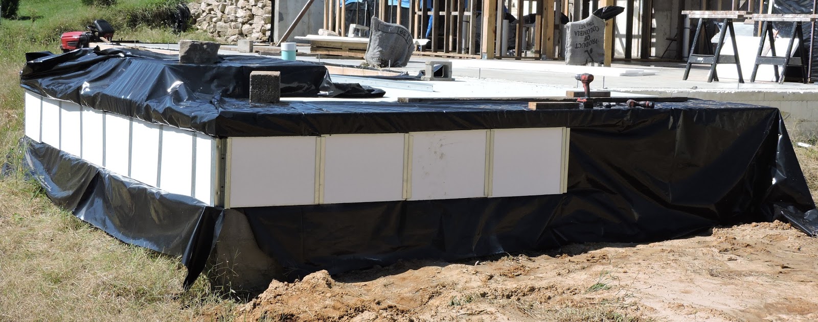
First layer of plastic sheeting with foam board on it
to help hold the top edge in place as it is stretched out
The best buy on 6 mil sheet plastic that I could find was at a farm and home center in the form of a 24' x 100' roll which was only a little more than what we needed for each layer of plastic going into the umbrella.  We cut and laid the first layer of sheeting over the sand base.  I previously had left two layers of plastic sheeting hanging out under the cement board/stucco covering for the house foundation and from under the rock retaining wall to the west of the house that needed to be woven into the sheeting of the umbrella. The first overlapped in shingle fashion the edge of the first umbrella sheet.

FOAM INSULATION
Most of the umbrella extends 16' feet from the house (20' would have been better but the
Most of the foam board in place and anchored for the night
placement of the solar collector and the under-dug embankment west of the house changed the rules). So the pattern for the foam insulation, based on Hiatt's prescription, was as follows:  4" thick for the first 8', 3" thick for the next 4', 2' thick out to the 16' periphery.  And in the few places the full 20' was possible, 2" thick for the last 4' (Hiatt recommended 1" but a sheet that thin at the periphery could be crushed too easily).


Balance of the foam in place; notice that the weaker white EPS
board in the first tier has been covered with the stronger XPS
 board in the second tier
In all, it took 70 sheets of 2" board, 20 sheets of 1" board -- all laid as much as possible so that the cracks between sheets in the first layer did not line up with the cracks in the second layer. Expanded polyethylene (white board in the pictures) is half the cost of extruded polyethylene (blue board) so about 40% of the 2" boards were EPS installed under the more rigid and relatively crush-proof  XPS.

Part of the hand work for the grade preparation was to make sure the first 2" layer of foam board butted up against the footing and was flush with the top of the footing.  In this way, the second layer rested on the footing and against the foundation wall so as to fulfill the requirements of a frost-protected shallow foundation. As mentioned above, the cement board/stucco cladding for the foundation wall was backed by two layers of plastic sheeting that stuck out quite a ways at the bottom.  The innermost layer overlapped in shingle fashion the plastic sheeting that laid directly on the sand bed.  As we will see in the next post, the outermost layer overlaps the top layer of the umbrella plastic.  The loose ends of plastic sticking out from under the stone retaining wall were handled in the same way.

Saturday, September 17, 2016

Design - Photovoltaic Array

Not "If" but "When"?
If we install photovoltaic cells, our electric company will allow us to use reverse metering to export electricity to the grid when we produce more than we consume. Unfortunately, unless the rules change, we will be credited at a lower figure when exporting (meter running backwards) than what we will pay for electricity when importing (meter running forwards).   Our goal is to break even with the power company without over-spending on photovoltaics but we won't know until we live in the house for awhile what it will take to do so.  Then we can size the photovoltaic array to our needs or perhaps decide that the return on investment for an array would be problematic.

Other Advantages of Waiting
In addition to monitoring our needs before investing in solar, there are other advantages to waiting.  Solar prices keep coming down and the panels almost certainly will be cheaper in the near future.  Utility company rebates and government rebates and tax credits come and go but I think the probability of this kind of help may actually increase over time pending which political party dominates at the federal and state levels.

Disadvantages of Waiting
Installing the panels initially would afford the opportunity of having them double as an
overhang for the second level clerestory windows, as shown on the accompanying
Click on drawing for expanded view
drawing, and thereby eliminate the cost of a conventional overhang.  The conduits and wiring from the array to the service panel would become part of construction instead of an afterthought.  However, we are more inclined to delay construction of the overhang for a couple of years anyhow in order to use the heat from the summer sun to jump-start the AGS system. Moreover, in order to function as a overhang for our latitude, the tilt of the PV panels would likely not be optimal for generating electricity.

Compromise Plan
We will probably decide to wait at least a year before investing in PV panels.
Instead of using the panels as an overhang for the second story clerestory windows, they will probably take the form of a free-standing array on the backfill behind the house that will be an easy electric hook-up and will be scarcely noticeable from the street. Free-standing, as opposed to attached, could include an upgrade to a mobile sun-tracking system to maximize solar gain.

Estimating Needs
The average rate-payer in the St Louis region uses 10,000 to 13,000 kilowatt hours per year, depending on whose figures one uses.  The 13,000 figure is about the average for the country as a whole.  The modern rental house in which we lived when first moving to Collinsville would be a better barometer of our electric usage than the 100-year-old farmhouse that we have since bought and occupy next door to the construction site. The rental unit had HVAC, electric range and electric dryer as the main demands on electricity.  We consumed 6,400 KwH/yr which is not much more than half the area-wide average, due in part to our sustainable-centric lifestyle and the reasonable size of the house.

Based on our experience in the rental unit, we are guestimating our electric needs in an energy neutral home to be 1,600 KwH/yr despite it being a larger house.  The load will be diminished, compared to the rental unit, by the intentional design of the house. Gas will be the choice for cooking and heating water (energy efficient tankless heater).  There will be no conventional electricity-scarfing air conditioning.  Abundant natural light in all spaces will minimize the use of lights during the daytime.  Most of the lighting will be task lighting.  General lighting will be controlled by manual override, dimmable motion activated switches so as to match use with occupancy. Energy-saving LED will prevail over CFL. Phantom loads will be minimized via strategic switching, not just for electronic equipment, but for mundane appliances like the toaster, microwave and clothes washer.  

Return on Investment
If an average consumer at 10,000 - 13,000 KwH/yr were to buy PV with enough capacity to make some dent in his/her energy consumption (forget about breaking even with the utility) the initial cost would be dependent upon how big a dent s/he wanted to make.  But the return on investment from energy savings would be protracted because her/his home was probably not designed for serious energy conservation.  My take is that adding PV to the average production home with 2 x 4 walls, or even 2 x 6 walls, and questionable attention to air-sealing, or to older homes like ours with no wall insulation, homes with solid masonry construction or homes with leaky windows and doors is like rearranging the deck furniture on the Titanic.

As counter-intuitive as it may be, PV for our super-insulated, passive solar project may not be a good investment.  Our consumption will be so low that the payback on a PV system that breaks even with the utility may not make sense.  On the other hand, it might.  The decision to invest in enough solar to be energy neutral might have less to do with cost-savings now as it does with insulating us from escalating energy prices in the future. If we add PV, it will be with the conviction that, with the current and future pressure on fossil fuel energy, the cost of electricity will only go up.

_     _     _     _     _     _

Update:  Summer of 2019.
It has become apparent that generous government incentives for purchasing PV are in danger of diminishing or disappearing.  So we are planning to invest in an array before the end of 2019.

Thursday, September 8, 2016

Construction - Second Line of Interior Bearing Walls

As explained in the previous post, it made sense to erect the interior bearing walls before starting the exterior walls.  Accordingly, that post went on to describe the first bearing wall -- situated a few feet inside the concrete earth-contact north wall.

This post details the second east-west line of structures, more or less in the middle of the house, that will support the front wall of the second story and the roof above it. This line is 55' long and comprises a complicated combination of a 2 x 4 wall, 15" thick truss wall, a header and a post and beam span over the living room-dining room-kitchen open floor plan.

(For a better understanding, it might help to consult the architectural drawings.  Click on them, as well as on photos here, for exploded views.)

Central Bearing Walls
The central bearing wall nearly complete; truss wall in foreground, post &
beam section in the middle; bathroom framing next and a dual header last
The south wall of the bathroom area comprises the 2 x 4 bearing wall section. Consequently, my first task was to build out the bathroom framing, including the joists that form the ceiling for the bathrooms and the floor for the second floor balcony office. The second story exterior wall will rest on the sub-floor on top of the joists.
Another view of the central bearing wall for better visualization of the
bathroom framing and the dual header to the left

Next, I had to build the north wall of the laundry area and a short section of the exterior truss wall extending east of it -- the section that will house the main entry eventually. Unfortunately, the wall contained pre-made wall trusses with plywood gussets that needed to stay dry and an imminent threat of rain caused me to wrap this section of wall in plastic before taking any photos.  Just as in the bathroom area, the second floor exterior wall will sit on the subfloor of the second story bedroom. Consequently, I had to install floor joists and
The subfloor on which the second story exterior wall will rest; the
narrow isthmus comprises the catwalk between the balcony office
in the foreground and the bedroom in the distance 
tie them into the front wall after it was under the plastic.


Catwalk
The second story exterior wall will also rest on the subfloor of the catwalk that bridges between the two second story rooms and extends westward over the master bedroom. The bridge portion of the catwalk is supported by two beams.  The short section of the catwalk that will overlook the bedroom will be supported by a combination of a header, a joist and a beam.  None of the catwalk could be built until all of the
Pre-made wall sections under cover
beams were in place.  Early on, the pre-made wall sections for the windows were stored under plastic in the master bedroom area.  Now they are in the way of completing the west end of the catwalk. I plan immediately to call in volunteers and lift most of them to the new second story for use in the south exterior wall. Then the remainder of the catwalk can be framed and subfloored to complete the central bearing wall.


Post and Beam Section
When designing the house, my fondest dream was to use salvaged barn timbers for the post and beam supports.  And my step-son and I were able to salvage a few good timbers and many not-so-good timbers from a 19th century barn.  We used the better ones for his house several years ago and the rest would be unsuitable for our needs.  So, in the interest of time and probably money (salvaged timbers can be pricey), I decided to scrap
Friends and family volunteers installing the heavier beam
the barn timber idea in favor of the man-made variety of which there were two options.


The plans called for 3 LVL's (laminated veneer lumber) fastened together to make the main beam.  They do not come in "appearance grade", meaning they are not pretty enough for a natural finish look and must be hidden behind something like drywall. An alternative was Glulams, another man-made product.  A natural finish on them became moot when the manufacture recently quit offering the option of a clean product with no identification information stamped on it.  To use them would involve much sanding to erase the markings for a natural look that even then would have been marginal at best.  The plans called for two sizes of beams. For the larger one, a Glulam beam would cost 28% more than an LVL's; for the smaller, a Glulam would cost 32% more than LVL's.

The posts specified by the drawings were 6 x 6s and the options at my lumberyard were pressure treated yellow pine, cedar and kiln-dried pine.  I chose the latter for a several reasons.  Pressure treated posts were unnecessary, more expensive than the pine and more likely to warp. Cedar, although it could have a natural finish, would not fit in with the other natural woods used in the house and it would be twice as expensive as pine.  The disadvantage of pine is that its natural look does not fit well either and will therefore need a drywall covering.  The robust hardware used to join the post and beams is anything but aesthetic and is best hidden behind drywall as well.   

Beam Construction
For bridging the 20+ foot gap between the bathrooms and the laundry area there needed to be two beams -- the "main" beam, to carry the second story wall and the "catwalk" beam, to carry the north edge of the catwalk.  The plans called for three 1 3/4" thick LVLs fastened together for the main beam supported on posts at both ends and one post midway.  Two LVLs were specified for the catwalk beam with no intervening posts.  

According to information online, the LVLs could be fastened together with through-and-through bolts, with construction screws or could be nailed together with 3 1/2" nails.  For
expediency and to save costs, I chose nails.  The longest nail my Paslode framer shoots is 3 1/4" which is just long enough for fastening 1 3/4" thick LVLs back-to-back.  The nailing pattern for a 12" tall beam was as follows:  Either two or three rows of nails (I chose three) with the nails in each row no further apart than 12" and no closer to the edge of the boards than 2".  Furthermore, the nails in each row should be driven from both sides so that the nails on a given side would be 24" apart in an alternating pattern with the opposite side.   In the case of the main beam that involved three LVLs, I nailed two together 24" OC then flipped them over, laid on another LVL and nailed it in an alternating 24" OC pattern.  The photo shows clamps to align the LVL's for nailing and the chalk lines guiding nail placement.

Despite manufacturer-applied "weatherization", I doubt that the integrity of the LVLs -- much like other manufactured wood products like plywood and OSB -- would hold up under my snail-like construction schedule that postpones getting them under cover for several months.  Therefore, my intention was to caulk any cracks and openings on the topside then paint them with Kilz undercoated in order to buy some extra time.  However, only the larger beam got painted; before I could l paint the smaller beam, we had the subfloor installed and I am assuming that its 500 hour rating against the weather will protect the beam sufficiently.  I do not regret having painted the larger beam because it is more vulnerable to sideways rain coming from the southwest and southeast.

Post and Beam Hardware
The hardware needed to join the posts with the beams was simplified by having beams long enough to span the entire 20' distance.  All that was required were off-the-shelf post bases to anchor the posts to the floor and keep them from touching the concrete and "T" braces (stand-alone post) and "L" braces (end posts) to secure the posts to the beams. The braces were pretty robust -- 1/4" thick -- and were fastened with the substantial 1/4 x 2 1/2" hex screws that came with the braces.