Thursday, October 22, 2015

Construction - Concrete Work - Plumbing and Electrical Rough-in Under Slab Floor

This is the fifth post on the concrete phase of construction and I apologize for its length but countless surprises challenged my DIY-ness and I would be remiss if I did not pass them along for whatever they may be worth.

With regard to the concrete per se, all that remained was to "sling" in the gravel sub-base and pour the slab floor. However, both tasks had to wait until the plumbing that resides below the concrete had been roughed in. The rough-in comprised not only the typical waste/sewer system but, in our case, the complete water supply system as well. And a considerable amount of electric could be roughed in before the pour. (Reminder:  Click on any photo to enlarge it.)

Waste Plumbing Rough-in
In conjunction with pouring the footing under the front wall of the house, a short section of 4" PVC pipe was inserted below the footing forms with a foot or so extending
Waste plumbing rough-in; notice the that it connects with
and exits through the section previously installed
under the footing
beyond the forms on both the outside and inside to facilitate running the sewer line. The same was done with 2" PVC for the water line. The 
outbound sewer line connected directly to the 4" but the water line merely used the 2" to hold space until a 1" water supply pipe between the house and the water main at the street could be installed.

Installation of the waste lines was a matter of trenching into the excavation just deep enough to have the correct fall for proper drainage.  The downstream pipes were well below the grade and the upstream most pipes were almost at grade. The only thing that complicated the installation was trenching through soil that was more like stone than dirt, thanks to a layer of what old-timers called "hardpan" that presented even more of a challenge by not having seen a rain for almost a month.  The good news was that it will make a great base on which to rest a house.


The installation of the waste system was less complicated than our iteration of the water supply system but it does give meaning to the old saying, "Trifles make perfection but perfection is no trifle".  It requires a lot of know-how and attention to detail.  Fortunately, between two friends and I, we had enough composite knowledge to put together a system that passed inspection the first time.

PEX Rough-in for Water System
Our water supply system comprises PEX (cross-linked polyethylene) tubing as much as possible.  PEX was used extensively in Europe for potable water several decades before finding its way to the US in the mid-80s (it was used in the US before then for radiant floor heating but not for potable water).  Even though it is not used yet by many tradesmen, it meets code in most places and has many advantages over copper and plastic pipes. (For a thorough discussion, go to design guide for PEX plumbing.) Its major advantages for our project are simplicity, significantly lower cost and DIY-friendliness.

The myriad design options for PEX are well covered in the above link.  Suffice it to say that, for our project, only two major decisions had to be made. First, do we run separate "home run" lines to each appliance and fixture or do we run trunk lines to areas like the kitchen and bathrooms then branch off to the individual appliance or fixture?  Second, do we run the lines beneath the concrete floor or run them more conventionally through the framework of the house?  We opted for home runs and below the slab.  Actually, the two are linked in that only continuous tubes of PEX, free of any fittings, can be buried.  By marrying home running with burying, the rough in for the supply system was essentially complete before pouring the floor, much less waiting for the framing to be done, and at a fraction of the cost of doing it later.

Underground Installation
If PEX is buried, it needs to be protected from injury while the rock sub-base is slung in place and the slab itself is poured.  Moreover, it must be protected from chafing where it enters and exits the concrete.  These issues are usually handled by trenching into the dirt, covering the PEX with dirt, sand or pea gravel and providing short sections of conduit for the tubing where it leaves the dirt, sand or gravel and passes through the concrete. My lack of experience made me cautious to the extent that I decided to use conduits for the entire length of each home run -- from a couple of feet above the floor level at the upstream end near the water main and water heater to a couple of feet above the floor at the downstream end in wet walls near the appliances and fixtures.  The loosely-fitting conduits gave me the security of being able to retrieve the PEX if, for some reason, it wasn't working out as intended.  Also the conduits obviated the need for trenching in that they were robust enough to lie on top of the grade and withstand the slinging of the rock sub-base and the weight of the concrete.  Most were buried in the gravel, a few showed after the gravel was slung but barely.  Using so  much PVC did increase cost but not significantly.

When the decision was made to enclose PEX in conduits, I experimented in the aisle of my favorite home center using a length of 1/2" PEX, various diameters of Schedule 40 PVC pipe and 45 degree fittings.  As a result, I decided that 1 1/2" PVC pipe would be the smallest possible diameter for ease of insertion of the PEX for the 20 - 30' distances required and for the bends necessary to enter and exit the concrete. And, supposedly, the tubing could just as easily be removed from the conduits in the future if necessary.

Wrong!  As a trial, I glued together the PVC for one of the longest runs, tried to push the 1/2" PEX tubing through it and found that it hung up and couldn't be budged past the rough edge of the second 45 it encountered.  I tried to run an electrical fish tape in from the other end so as to pull the PEX and it too hung up immediately. Consequently, it was necessary for all 20 home runs to push the PEX past each fitting before gluing the fitting.  Fortunately, the PEX was not effected by the PVC primer or the adhesive so there was no danger of gluing the PEX to the conduits.  If a PEX line needs to be retrieved and replaced in the future, the thought comes to mind that a plumber's snake would negotiate the rough fittings and could be used as a fish line for pulling the tubing through the conduit or, better yet, the old tubing could be used to pull the new through the conduit.  

As it turns out, 1 1/2" PVC was the right choice.  PEX is a stiff material with a strong memory that wants to stay coiled up. Over distances of 35", 1 1/2" barely allowed the PEX to be pushed through.  Even the 10' sections of pipe between fittings offered sufficient resistance that I think a smaller diameter conduit could not handle easily. In one instance, I tried pushing two PEX tubes through in tandem and quickly decided that the effort was not worth the savings on conduit.  

Controlling the Entry and Exit Points for the Conduits
The biggest challenge to running the PEX system was to have it enter and exit the concrete at a perpendicular angle and be properly located inside the wet walls adjacent to fixtures and appliances.  To have any part of the conduit exit outside the wall would be unacceptable. 

The supply system rough-in completed:  Bathrooms to the
left, kitchen island sink and laundry to the right; future
manifold area in the background; second kitchen sink out
view to the right
Consequently, to control the ends of the conduits,  I shop-made salvaged 2 x 4 supports.  One set had 2 1/4" holes for the conduits and an identical set had 7/8" holes for the PEX.  Five foot sections of 4" PVC pipe were used as posts to hold the 2 x 4s in place.  Since the buried portion of the posts would remain in the concrete, I chose plastic posts over metal to eliminate the possibility of the metal rusting, expanding and cracking the concrete.  Wood posts were out of the question for termite reasons. Eventually, the PVC posts will be sheared off flush with the floor and filled with concrete. In many cases, the stub-outs of the waste plumbing rough-in could be used in lieu of or in tandem with temporary posts.  I chose 4" posts only because 2-hole metal straps were available for fastening the 2 x 4s to them and the pipes were left-overs.
Manifolds with cut-offs for each home run

Looking ahead, the beginning ends of the PEX lines will be joined to copper manifolds with individual cut-offs for each line, much like a circuit breaker for each electrical circuit in a service panel. Eventually, copper pipes will run from the tankless water heater to the hot water manifold(s) while PEX will suffice between the water main shut-off and the manifold(s) for the cold water supply. 

The PEX at the fixture/appliance end of the lines will be supported by brackets attached to the framing and stubbed out of the wall for uninterrupted connection to faucets and appliances.  Or perhaps, I will use a copper stub out. In either case, only three or four fittings per line will be necessary -- two at the manifold end and one or two at the fixture/appliance end. And, of course, there will be no need for cut-offs adjacent to the fixtures and appliances because cut-offs are built into the manifolds.
Bracket-supported PEX for direct
connection to faucets
PEX with copper connection for faucet

Materials Cost
The rough-in cost for the waste and supply materials was only $300. However, when the cost of PVC conduits was added, the total cost was $841. I consider the $541 for the conduits to be cheap insurance against damaged PEX lines and not having the option of retrievability in the future.

Other Advantages to Home-running
Compared to trunk and branch systems, the home run system requires more PEX tubing but far fewer fittings. Since the cost of tubing is much less than the cost fittings, home running is cheaper. And, a traditional copper pipe system would cost even thousands more due to the higher cost of copper and, for underground installation, someone who is capable of soldering with silver solder. Another advantage to an underground home run system is quicker hot water. Compared to a home run system run through the framing, the quickness derives from the shorter distance between the water heater and the fixtures.  A trunk in a trunk and branch system requires a larger pipe (usually 3/4") than the branches (1/2").  This means that, compared to a home run system with all 1/2" pipes, there is more cold water in the system to be pushed out by the hot water.

Home Run Electrical Conduits
Electrical conduits from future breaker panel area to areas
that would be hard to reach by running wire through the
 framework of the house, e.g., the island sink in the kitchen
to the right in the picture or the front wall of the house to the
left
After the water supply rough-in was complete, one last job remained before pouring the floor -- running electrical conduit.  Being able to make long runs sub-concrete simplified getting service to areas remote from the future breaker box, especially where the open floor plan (living room, dining room and kitchen) and cathedral ceilings would significantly complicate running wires through partitions and ceilings. I ran 3/4" conduit for two reasons -- being unfamiliar with pulling wires through conduits, I figured bigger was better and 3/4" gave the option of  pulling two or three sets of wires when only one or two might really be necessary.  If one or two sets remain unused in the future, there would be no downside
Stub-in for future floor receptacle in the form of a space-
holding tin can; the black pipe in the background, the water
 supply line coming in from the street, is wrapped with pipe
 insulation to keep the water cool as it passes through the
thermal mass under the floor when it is warmed by the AGS
 system eventually
since I fell heir to several spools of wire when helping to ready our former church for a remodel. 


The need for a floor receptacle was met by using a tin can to hold space during the pour.  A hole saw in the drill press, provided access for the conduit  through the bottom.  The rotating laser located the top of the can 2" above the pour, a stone supported it and a length of rebar piercing the bottom the can and driven into the soil at an angle stabilized it.

*     *     *     *     *     *     *     *
October 2019 Update
The final rough-in for the plumbing was completed four years later.  Here is the link to the later post on the plumbing rough-in.  Of special interest is its description of the manifold, tankless water heater and the automatic overflow prevention, all part of the PEX home-run system.

Friday, October 16, 2015

Construction - Concrete Work - Insulated Concrete Forms

This is the fourth post on the concrete phase of construction.  It details the unconventional foundation under the stick-built walls.  The first post on concrete work covered the excavations for the footings.  The second dealt with pouring the wide footings and concrete walls.  A third detailed the narrow footings under the stick-built walls.  Here we dwell on the rather unique and unconventional foundation wall, poured in insulated concrete forms to support the stick-built walls.  (Click on any photo to enlarge it for closer inspection).

Shallow Frost Protected Foundation
Our foundation is based on a recent "green" innovation that has actually found its way into the International Building Codes.  It is called a "shallow frost-protected foundation" (see the earlier post on shallow frost-protected foundation).  Instead of the top of the footing for the foundation being below the frost line, it is protected by insulation so that it can be much closer to the surface.  Our plans call for a 20" foundation wall, i.e., the distance from the top of the footing to the top of the foundation is 20".  For termite reasons, the code calls for an 8" separation between the soil and the wood elements of the structure.  If this dimension is subtracted from the height of the foundation wall, the top of the footing is only 12" from the grade instead of the +/-30" needed to get below the frost line.  This represents a 46% dividend in terms of embodied energy in the concrete as well as a few dollars saved on the volume of concrete.  However, the forms do not come cheap (a little over $1,200 for the 164 linear feet  20" high).  It would have been almost twice as much if the forms were used to pour a conventional foundation that reached below the frost line.  However, it must be said that, for a first-timer, the installation was unexpectedly time-consuming and frustrating, due largely to the unevenness of our footing.


Amvic Insulated Concrete Forms
The brand of  insulated concrete forms (ICFs) that I selected was the Amvic System because it were available from a local supplier and was manufactured in Missouri, both of which help to minimize embodied energy which is an important sustainability issue.

Installing the Insulated Concrete Forms on the Narrow Footing
Let me say upfront that our installation had little in common with that detailed in the "ICF Technical & Installation Manual" for the Amvic System.  The need for improvisation was entirely my fault by not getting the footing perfectly level throughout.  In retrospect, it would have taken rented metal forms installed with huge precision to have met Amvic's spec of 1/4" variance for levelness.  But salvaged  2 x 8s, despite being a lot more work to install, not always straight-edged and impossible to install precisely, were free and produced a leveler footing than would have been possible by pouring directly against the soil in a trench.

The Amvic ICFs are available for wall thicknesses of 4" to 10" of concrete with 2 1/2" of expanded polystyrene ("styrofoam") on either side,  The styrofoam serves first as the outside and inside forms into which the concrete is poured.  The "Dixie Cup" walls are strong enough to handle the concrete by virtue of internal webs that hold the two sides together.  Secondly, the forms stay in place after the pour as R-22+ insulation.  Our ICFs were for 8" walls such that the overall thickness, styrofoam included, was 13".  The 20" height for the wall was achieved by using one course of blocks 16" high then adding a 4" so-called "height adjuster" course to the top.  The smooth top of the height adjuster also facilitated screeding the top of the wall when the concrete was poured.

Our house plans give the dimensions of the foundation wall in terms of the exterior plane of an 8" wall and the batter boards had been set to these exterior dimensions. The ICFs then had to be installed on the newly-poured footing so that the concrete poured into them matched the batter boards.  To this end, mason lines were strung one last time between batter boards so that the equivalent of corner posts could be established and marked with concrete screws on top of the footing.  A chalk line was then tensioned between screws and snapped to give the position of the inside edge of the exterior styrofoam, which is to say, the outside edge of the concrete when it is poured inside the styrofoam.
Chalk line wrapped around a corner screw and
 ready to snap for a layout line.

We used a technique for aligning the forms that the installation manual recommended, viz., 2 1/2" steel drywall tracks for precise positioning of the ICFs along the chalk line. The tracks were fastened with Tapcon concrete screws on the chalk line so that the outside styrofoam of the ICFs, when seated in the track, would give a perfectly straight wall.  But "straight" is not the complete answer -- the wall has to be level if the foundation is to be level.  Despite working so hard using wood forms to control the levelness of the footing, there was a variance of about an inch over 164 linear feet. Therefore, the variance had to be finessed as the ICFs were installed through a combination of shimming (raising) under the low spots and shaving the bottom of the ICFs (lowering) over the high spots (all of which was much more time-consuming than expected).

Leveling the ICFs Longitudinally 
Thank goodness for a rotating laser when working alone.  I used it first to survey the top of the entire footing at +/- ten foot intervals to see how much variance there was and where the highs and lows were located.  Based on that data, I picked a default height that was weighted towards shimming (raising up) rather than trimming the bottoms of the ICFs.  As a consequence, the highest shim was +/-3/4" and the most that the bottoms of the ICFs had to be trimmed was +/-1/4" and the latter occurred only over 10-15' linear feet distributed over three areas.  

Installing the Metal Track
The first task was to drill holes in the tracks so they could be screwed to the footing with Tapcon screws. The easiest way to do so was ahead of time with a drill press.The installation was started where the track could be fastened without shims at the default height.  As the installation proceeded around the footing, the following steps emerged as the best approach ("proximal end" means the end next to the last section installed and "distal end" means the end farthest from the last section):

-  Lay the track on the chalk line
-  Fasten the proximal end first guessing (based upon laser readings) as to the amount of
Friend, Glen, leveling
the track with laser
 guidance.  Click on
 the photo to see the
 shims under the track
 shimming necessary and placing the shim(s) adjacent to the screw rather than drilling through them 
-  Since part of the shims will remained in the concrete avoid using wood shims to avoid attracting termites; use plastic shims, either store-bought or made from styrofoam trimmings
-  Fasten the distal end of the track on the chalk line without regard to shimming
-  Check the proximal end with the laser; loosen the screw, adjust the shimming as necessary and retighten the screw
 -  Check the distal end with the laser, loosen the screw and shim as necessary
 -  Through each of the intervening pre-drilled holes in the track, drill holes in the
 concrete
 -  Add the screws; shim beside each screw, guessing as to the thickness; tighten the screw and check with the laser; if necessary, loosen the screw and finesse the shim height
-  Helpful hint:  Before shimming, press down on the track above a screw hole with the laser measuring rod to get a read on the shim thickness required then add the screw and the shim; doing so eliminates some of the trial and error and tends to speed up the process.

Leveling the ICFs Transversely 
So the above efforts leveled the outside styrofoam but the inside styrofoam was still a mess. The ICF blocks are sufficiently rigid that the inside foam goes along for the ride longitudinally but they still need leveling transversely. And, of course, transverse leveling also plumbs the wall.  We tried two methods but the one that worked best was to wait on the inside shims until the forms were leveled longitudinally.  Then, in conjunction with plumbing and leveling the forms, shims were added as necessary.

Attaching the Forms to the Footing
The disadvantage of opting for more shimming and less shaving to achieve levelness was that there was a space between the metal track holding the outside styrofoam and even more space under the inside styrofoam that did not have a track taking up space.  The manufacturer recommends using a proprietary foam and sprayer to fill the space and "glue" the forms to the concrete. The customer service person at the local supplier suggested, since our project was a one-time and small project, not to invest in the sprayer but to use a spray adhesive instead. It wasn't until we were ready to use it did we realize that the styrofoam must be in intimate contact with the concrete for the adhesive to work.   So how do we DIY a way to fasten the forms to the footing and obliterate the gap under them so that the concrete does not raise the forms or leak out under them? 

(This then is the point of departure from the technical manual).  First we ripped enough 1 x
The 1 x 2s were fastened to the concrete.  To the right,
one layer sealed off the bottom but, to the left, two
layers were necessary due to unevenness of the footing.
2s from salvaged lumber to circumvent the entire ICF setup on both sides, butted them against the forms and fastened them to the footing with Tapcon screws.  This stabilized the bottom of the forms from the lateral pressures of the concrete during the pour and largely sealed off the space under the forms (there was the equivalent of 70 linear feet, randomly situated, that needed a second layer of 1 x 2s and 30 linear feet that sat directly on the concrete). However, the 1 x 2s did not keep the forms from lifting as would be expected from adhesive foam recommended by the technical manual.


While actually exceeding the manufacturer's specs for spacing of vertical bracing, we used 2 x 4s resting on top of the 1 x 2s and stopping just short of the top of the wall. The verticals were drywall-screwed into the plastic webs that tie the two sides of the forms together -- the same ones that serve as "studs" for fastening the exterior and interior finishes later. Then we used drywall screws and Tapcon screws to anchor to the footing by toenailing the verticals to the 1 x 2s or, where they did not exist, directly to the footing.  As recommended by the manufacturer, the basic 16" x 48" ICF straight blocks in the first course were tie-wired together then extra verticals were added where adjacent blocks were still a little unstable or unlevel.

Strongbacks and Lateral Bracing
In additional to vertical bracing, there needs to be lateral bracing.  We chose to do it on the interior of the forms so as to have it out of the way of pouring the concrete. The verticals on the interior of the forms provided solid fastening for the braces.The verticals on the exterior of the forms, though anchoring the forms and supporting the strongbacks, did not receive
View showing the verticals, strongbacks and braces
any braces since 
bracing was necessary only on one side of the forms.  The exception was a "T-wall" that intersected the exterior wall.  Here exterior bracing was necessary because, without the bracing, the weight of the concrete in the leg of the "T" might cause a blow-out.

Strongbacks would have been overkill if the wall had not been topped off with the 4" height adjusters that gripped the course below rather tenuously and looked suspiciously vulnerable to displacement during the pour.  So, as an insecure amateur, I needed the strongbacks as insurance..

Garage Door Cutouts
The garage floor will overlap the foundation below the two garage doors.  Therefore, the
Cutouts for the garage doors 
ICF forms needed to be 9" shorter under the doors, which is to say the forms had to be shortened by that amount.  Despite leaving the 4" extensions off, the blocks below needed to be shorten 5" but doing so presented a dilemma in that the all-important tops of the webs in the forms would have to be cut which would severely weaken the walls of the forms.  I elected to
Garage door area - final configuration
cut 
away only the unsupported foam between the webs, thinking that I could finesse the cutouts after the concrete cured.  And the vertical rebars that were fine for the rest of the foundation were too long at the cutouts.  It was a simple matter to shorten them after they were stabilized by the concrete.
Rebar extending into existing wall

In order to transition the concrete from the higher foundation walls to the lower cutouts, 2 x 8 pressure treated blocks-outs were cut at 8" to fit inside the ICFs. They were anchored in place with 6" TimberLok construction screws that pierced the vertical braces (existing or added specifically to support the block-outs) and the foam before screwing into the treated members.  The block-outs were held at least 1 1/2"  back from the eventual rough door opening so as to accomodate two-by framing for the door opening and still maintain a 9' opening.

Tying Walls Together
The joint between the existing concrete walls and the new foundation wall was a "cold joint", meaning they merely abut each other but are not physically joined. In order to keep the relationship between them from shifting, the rebar from the foundation wall was extended into the existing wall by drilling holes a couple of inches deep for the rebar in the foundation wall. 

Pouring the ICFs

It took 5.5 yards of concrete, a conveyor truck and five volunteer workers to pour the forms
Forms poured and anchor bolts in place
with relatively little effort -- definitely a DIY-capable endeavor.  And I am happy to report that the installation of the ICFs was sufficiently robust to eliminate any potential blow-outs.


Quality Control Issue with the ICFs
The ICFs are understandably fragile. Some components were damaged in transit and were unusable.  The height adjusters that were 1/8 to 1/4" shorter than the straight blocks and had to be split in half
Poured foundation after bracing removal
and, even then, somewhat forced to place. The design of the corner blocks have been upgraded for better retention of cladding materials but the height adjusters have not been ungraded.  Consequently, both the adjusters and the corner blocks had to be modified with a knife to maintain levelness. Cutting and fitting two halves of the adjuster separately left space that I filled with minimal expanding spray foam, which actually may have been an advantage in that the adjusters were glued together and perhaps more stable.


Would I use ICFs again?  In a heartbeat, but only after more research before buying.

Saturday, September 26, 2015

Construction - Concrete Work - Narrow Footing Under Stick-Built Walls

This is the third post on the concrete phase of construction.  The first post covered the excavations for all of the footings.  The second post covered the wide footing under the concrete walls.  This post deals with the footing under the stick-built walls. (Reminder:  Click on any photo to enlarge it.)

Pouring the Concrete Walls
Here's where I had to stand aside and watch.  Jamie Schulte and his crew of +/-8
Forms in place; ready for the pour.
strongbacks (sorry for the pun -- "strongbacks" are integral to the bracing of concrete forms) took two days to set up the forms, a half-day to do the pour and another day to dismantle the forms and pack them off.  The wall took 36 yards of concrete, including one yard to prime the pump on the truck.


Once the concrete guys were gone, I dismantled the forms for the footings and turned my attention to the footings under the stick-built walls.  
Pouring the wall from a pump truck


Narrow Footing for the Stick-Built Walls
Unlike the wide footing under the concrete walls that was poured largely without forms, the narrow footing was poured in wood forms entirely.  The choice of wood forms was based upon the low tolerances specified for the insulated concrete forms  that will be used on top of the footing for the foundation walls.  The specs for level call for no more than 1/4" variance.  However, we were later to find out that our best efforts at forming up and pouring a level footing still yielded a variance of 7/8" over the span of 164 linear feet of footing.

For an 8" thick concrete wall, the code minimum for the footing is 8" thick and 16" wide. The forms were set for 8" thick and slightly more than 16" wide using salvaged 1 x 8s lubricated with diesel oil.  For the +/-20' section over the conduits for the solar collector, the thickness was increased to 16". The design of the forms was taken from Chapter 7 in the book, "Carpentry & Building Construction; A Do-It-Yourself Guide" by William P Spence.  It took several days to get the forms ready for the pour.  My step-son and a friend, a journeyman carpenter, contributed 2 1/2 man-days towards building the forms.  Surprisingly, it took me as much time to wire in the rebar as three of us took to build the forms.

Rebar Configuration
As with the wide footing, bolsters with plastic sheeting under them were used to support

the horizontal rebars at a height of 4" and at intervals of 4'. The horizontal rebars were wired to the bolsters 8" apart. The latter dimension was easily attained from the 8" distance between two of the vertical elements of the bolsters.


In earlier times, a rhomboidal-shaped two-by-four was typically nestled into the top of the fresh footing concrete to create a "keyway" depression into which the base of the concrete wall locked.  That practice seems to have been abandoned in more recent times in favor of "L"-shaped rebars projecting upward from the footing to be incorporated in the wall.  In our case, the plans called for vertical rebar on 2' centers (which matched the situation in the wide footing for the concrete walls as described in the 
Since the 20' section of the footing over the conduits for
 the AGS system is essentially a beam, the forms provided
for twice as much concrete and twice as much rebar as
 the rest of narrow footing.  Notice the rebar (painted 
orange) protruding from piers
second post).  All rebar was #4, i.e., 4/8" = 1/2" in diameter.


The vertical "L-bars" could not be plunged into the fresh concrete randomly but had to be
The poured wall and the forms for the narrow footing
ready to pour; notice the deadmen behind the wall.
positioned accurately in order not to interfere with the webs in the insulated concrete forms (specs called for them to be situated on multiples of 6"). So-called "spreaders" were used on top of the form boards on 2' centers but not to brace the forms as typically done -- the forms were rigid enough without them.  Instead, the L-bars were wired to them for support in a vertical direction while being wired to the horizontal rebar for support in the other direction.  As soon as the concrete was poured, the spreaders were

removed so they did not interfere with screeding off of the fore and aft form boards as Pat is doing in the photo below. As the concrete gained stiffness, the L-bars were straightened as much as possible with the intention of making them perfectly vertical by bending them later if necessary.  Later, when the forms were set up, a few rebars had to be redirected but none had to be cut off and repositioned.

Pouring the narrow footing was definitely within the grasp of the DIYer. Five of us amateurs were able to off-load the concrete and get it screeded before it began to set -- but
Friend, Pat, and family volunteer, Archie, screed;
off-loading concrete utilizing the extra 14' of chute
barely.  And, unlike the pours for the wide footing and the wall, the forms could be reached by the ready-mix truck with a conventional chute plus, in one area, a 14' chute extension.


The bottom photo is included to show the relationship of the narrow and wide footings.  The insulation was cut away and shallow holes were made in the wide footing into which the horizontal rebar in the narrow footing fitted.  The concrete in the narrow footing cold-jointed with that of the wide footing.  

Fortunately, for the first time this year, rainfall has been, for over a month, less than normal providing the perfect weather for the concrete work.  We were able to get the narrow footings poured while the dry weather persisted.  My hope is that we can get the foundation walls up while it is still dry.

Parenthetically, the Building Director who inspected the forms before the pour, was very complimentary, saying something like "this is the way it is supposed to be done and rarely is".

Foundation French Drain
If I am not mistaken the code that Collinsville is using, requires a footing/foundation French drain -- as well it should.  In
Junction between wide and narrow footings.  Notice he
loose end of the French drain and the fact that it is
bedded in sand instead of rock.
our situation however, it is probably overkill. With the final grade behind the concrete earth contact wall severely sloped northward, an insulation/watershed umbrella under grade extending 20' from the wall plus seven French drains 10' below the floor level, it is highly unlikely that water will ever reach the level of the footing once the house is completed.  If I thought otherwise, I would not have compromised on its installation.


The one thing we did that was not a compromise was to trench for the drain next to the footing so as to keep it below floor level and slope it gradually to daylight.  (Apparently, it is not uncommon for the drain to be laid on top of the footing against the wall.)  But, that said, there were a couple of compromises.  I used corrugated and perforated drain pipe with a sock on it from the local big box home center knowing full well that the sock will not filter out our wind-blown loess soil forever, that it will eventually allow the drain to clog with silt. Moreover, instead of bedding it in clean stone, I used sand, which will work as well and almost as long as stone before clogging with silt.  

Since I plan to backfill in 5' layers and let nature do the compaction, as opposed to shallow lifts and mechanical compaction, the umbrella and final grade will be months away. Therefore, an atypical rationale for the drain was advocated by the concrete contractor. Even if it functions only temporarily, it will serve to keep the backfill drier and reduce the pressures against the wall as the backfill compacts over time.  In this context, the compromises become acceptable.

Thursday, September 24, 2015

Construction - Concrete Work - Wide Footing for Concrete Walls


As described in the first post on concrete work, there are two kinds of footings -- one for the stick-built walls and another for the concrete walls.  This post visits the wide footing for the latter.

Wide Footings
The footing under the earth contact concrete north wall required a hefty footing, plus five deadmen, because (a) it is very long, (b) it will have only one "T-wall" bracing it, (c) most of it is two stories high and (d) it will be backfilled to the top. Therefore, it is a retaining wall on steroids rather than a typical "basement" wall.  The footing for it is 4' wide and 2' deep and poured directly against the earthen walls of the excavation except for the top few inches that were formed up with lumber.

Wood Forms
Salvaged 2 x 4s were used for the forms but they could not be installed in such a way as to seal off completely the gap between the forms and the adjacent grade. Also I wanted to keep the lumber as clean as possible so it could be used later in construction.  So, in order to kill two birds with one stone, I stapled 30# felt (Craigslist-bought for pennies on the dollar) over the tops of the boards and let it hang down along the walls of the trench.  In this way, the boards did not come into contact with the concrete and the gap between the forms and the grade was sealed off.  (Jamie Schulte, the concrete contractor, said the heavy felt was overkill, that 6 mil plastic would have worked as well).

Horizontal Rebar
The rebar for the footings presented two learning opportunities.  First, the "L-bars" that are tied to the horizontal rebars and protrude upwards to tie the footing to the wall should not be DIYed.  The local supplier, who cut the rebar to size and bent it, charged only the per-foot price for the rebar without adding a surcharge for cutting and bending.  The second learning opportunity was my naive choice of plastic high chairs to support the horizontal rebar in the trench -- they were a joke.  Their selection was based upon trying to avoid steel in contact with the soil to avoid the potential of its rusting, expanding and cracking the concrete. 


Bolsters
After trying to stabilize the rebar on individual plastic high chairs (talk about the domino effect -- a nudge to the rebar at the east end caused the entire rebar assembly to fall off of the chairs clear to
Good view to show the wood forms covered with felt paper
and the configuration of the rebar. Notice the outcroppings
 in the form for the deadmen.  (Click on the photo to 
enlarge it for detail.)
the west end of the trench  over 90' away). When I mentioned to Jamie ahead of time that we were using the plastic high chairs, he was not critical but did say that he used what is known in the trade as "bolsters" but what is called "continuous high uppers" on the supplier's website. They come 5' long and have to be cut to length. Professionals use gas-operated portable abrasive cutters; I gang-cut them with a metal cutting blade in a reciprocal saw.  Then, in order to obviate the potential for steel contacting the soil, I cut rectangles of 6 mil plastic sheeting to slip under each bolster.


Rebar Configuration
For the 4' wide footing three courses of horizontal rebar were necessary.  First the two outer courses were tied to the bolsters then short pieces of rebar were tied at right angles to the tops of the outer courses.  Then the third, i.e., middle course, of horizontal rebar, was tied on top of the short bars.  The bolsters were the tallest available (6") in order to raise the horizontal rebar as high as possible in the exceptionally thick footing. 


Pouring the footing with the help of a conveyor truck
and rotary laser.  The view is from the NE corner.
The vertical "L-bars" were tied to the horizontal bars on 2' centers.  The short end of each "L' rested on one of the outermost horizontal bars, passed under the middle horizontal bar with the vertical portion butting against the middle bar, thus centering it in the wall. Once wired to place, they were secure at the lower ends but were tipsy at the tops. So, another course of horizontal rebar was used to tie the tops of the "L-bars" together and keep them upright. The fact that the rebar turned the corner at the west and east ends helped to keep the entire assembly stable.

The Pour
The pour might have been within DIYer capability but I am glad that I delegated it. The
Finishing up the pour; notice the outcroppings for the
deadmen.
access to the forms was limited to the extent that a conveyor truck was necessary and, instead of screeding off of the form boards, it was poured level without screeding using a rotating laser. Altogether, 37 yards of concrete went into the footing which is slightly more than the wall itself took.


Insulation
Click on either of the bottom two photos to enlarge it and notice the pink insulation lining a small section of the outside wall of the trench and serving also as the form between the wide footing and what will be the narrow footing for the stick-built walls. The vertical insulation is critical for the shallow frost-protected foundation (post on foundation design) that is being used here and for the rest of the house.  And it should go without saying that the same configuration for the insulation was used at the south end of the footing for the west wall.

Friday, September 18, 2015

Construction -- Concrete Work - Footing Excavations

This is the first of at least a couple of posts on the construction of the footings, concrete walls and slab floor.  (Click on any photo to enlarge it.)

Earth Contact Walls
Previous  posts chronicled the amount of earth sheltering and specifically the north wall. In the end, the earth contact walls were poured in concrete which turns out to be a good decision but way beyond anything an inexperienced DIYer ought to tackle.  

Since the north wall will be supported internally by only one "T"-wall and most of it backfilled to a depth of 12', it had to be treated as a free-standing retaining wall.  The footing had to be 4' wide and 2' deep and the wall had to be 10" thick.  In addition, it had three deadmen extending northward 5' that were 10' thick and 8' high.  By turning the corner and extending the wall for 20' on the west side and 5' on the east side, the extensions also served as two more "deadmen". The final design was not that of the highly-paid structural engineer that stamped our plans but that of the experienced concrete contractor that we hired.

The engineer's design called for a 12" thick wall with an 8' footing and a fortune in #5 and 6 rebar mixed with the more common #4 rebar.  By using the deadmen and by overlapping the footing with the slab floor, as advocated by Jamie Schulte, the contractor, the wall is far more stable at much lower cost.  Our Building Director, the local permitting person, agreed.

Footing Excavations
Trenching for the north wall footing 2' deep and 4' wide
In terms of width and thickness, a different footing would be necessary for the concrete wall versus the other stick-built walls.  The footing for the concrete walls, as mentioned above, needed to be 4' wide and 2' thick.  The footing under the stick-built walls needed only to be 16" wide and 8" thick.  Due to the 2' thickness of the wider footing, the depth below floor level for the two kinds of footings was the same so all the trenching could be done at the same depth with a 4' wide backhoe bucket.  The wider footings under the concrete walls could then be poured directly against the earthen walls of the trench with minimal wood forming at the top.  For the narrower footing under the stick-built walls, the wide trench provided the room we needed to set and brace the wood forms.

Batter Boards
I used the house plans to set up batter boards, first, to guide Brian Hayes, our excavation
Mason lines and corner posts delineating stick-built walls
contractor, as he did the final grading and excavating for the solar collector then to guide the placement of the piers under the front wall of the house.  But their real value came when laying out the footings. Contrary to most of the references I studied, the batter boards had to be positioned abnormally far away from the action in order to be out of the way of the backhoe and concrete trucks, which was no big deal except for creating longer mason lines that could only be used accurately in the absence of any wind. (As an amateur, I did lose sight of the fact that the north batter boards would eventually be rendered moot by the concrete wall in front of them and would have to be relocated in front of the wall before the foundation walls could be properly sited.)

Identical trenches for wide and narrow footings; Brian uses
track loader to backfill pit between house and solar collector

I used taut mason lines running between boards and the equivalent of a plumb-bob to find the outside corners of intersecting walls and drove stakes under the plumb-bob and then a nail on top of the stakes to mark the intersections precisely.   I ran another line at the bottom of the trenches 5" inside the prospective 10" concrete walls and 4" inside the prospective 8" foundation walls under the stick-built walls to delineate the middle of the footings.  I then used marking paint alongside of the string to transfer the middle of the footings to the bottom of the trenches.

Leveling the Narrow Footings
The tolerance in footing height for the insulated concrete forms (ICFs) that we are using for the foundation walls under the stick-built walls is tighter than for concrete foundation walls poured in conventional forms -- actually a variance of only 1/4". Then, when the ICFs are set dead level on the footings and filled with concrete, the concrete could be finished flush with the smooth tops of the forms to give a perfectly level foundation throughout the house.

The reason for opting for footings poured in wood forms, as opposed to pouring directly into the trenches as is commonly done and was done for our wide footing, was for more precise leveling.  In order to accomplish it, I used the rotary laser as a guide for fastening a short piece of 1 x 4 to each corner post to delineate the exact height of the form boards -- therefore the final height of the footing itself.  Using straight boards and setting all of them exactly level with one another was extremely important in assuring a level foundation wall and, since the concrete floor would be screed level with the top of the foundation wall, assuring a level floor as well.

Parenthetically, l should add a caveat.  The decision was made later to increase the depth of the concrete slab from four inches to five to give it more strength.  The extra inch could be gained by either reducing the amount of gravel base under the slab from four to three inches or by increasing the height of the foundation wall by raising the footing by one inch. I elected the latter for reasons yet to be discussed in a subsequent post.

Tuesday, August 25, 2015

Construction - AGS System for Passive Solar Heating and Air Conditioning - Cont'd Lots More

This is the third post on the design and installation of the AGS system.  Since our iteration of the solar collector is one-of-a-kind, this post runs long in order to hit all of what I consider to be the important details, including some mistakes.  

The first post detailed the conduits that carry the heat from the summer sun to the thermal mass under and around the house.  The second post focused on size of the solar collector and the excavations necessary to build it into the slope in front of the house.  This post deals mostly with the construction of the shell for the collector, connecting the conduits to the collector and closing up the excavation. (Click on any photo to enlarge it..)

Walls
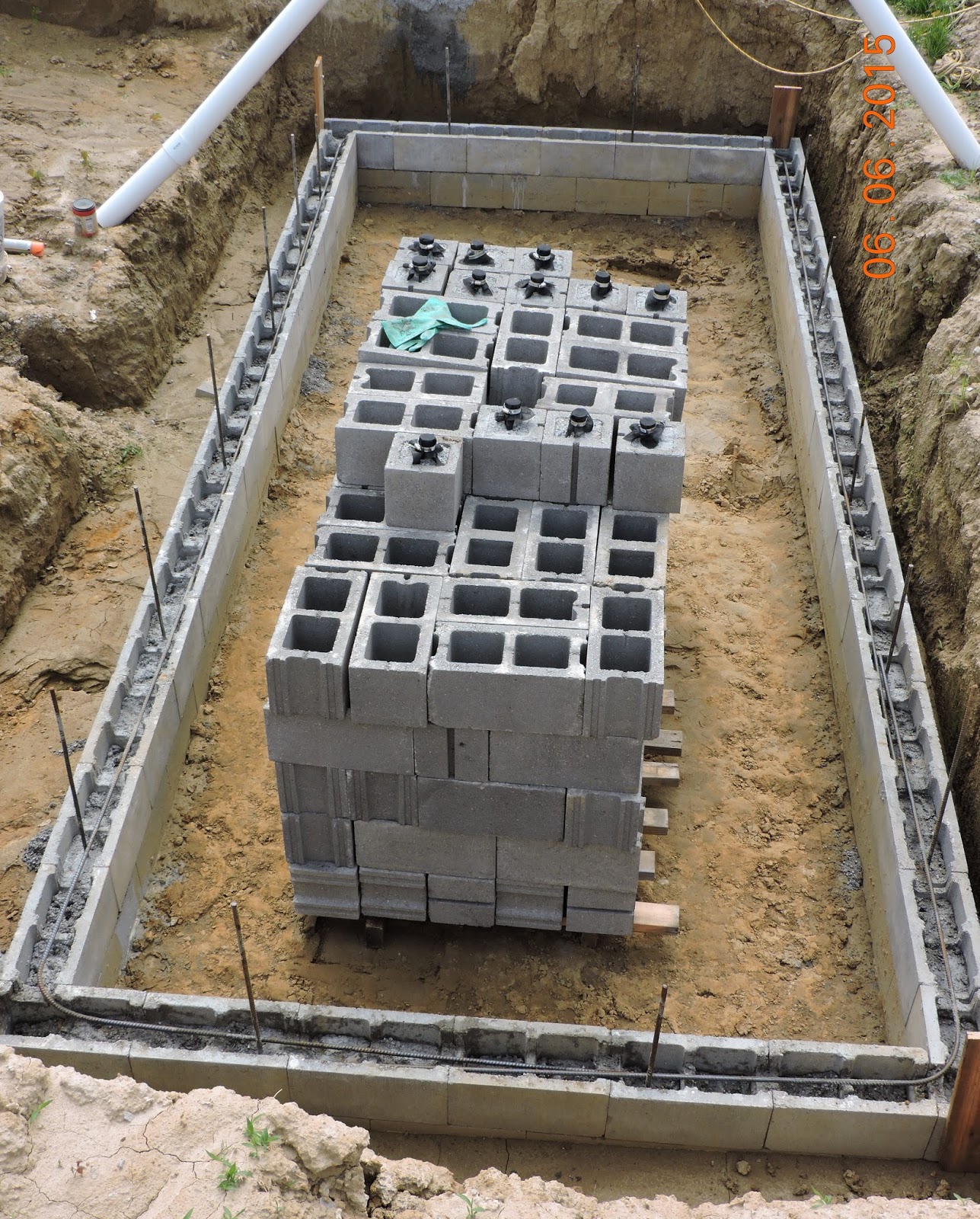
Since the collector is buried in the ground, the walls have to brace several feet of backfill. It could have been constructed with poured concrete on a poured footing resting on virgin soil, similar to a foundation wall.  In order to save money and to be able to design it as we went, I opted for dry-stacked concrete blocks resting on virgin soil and sand.  The first course
Bond beam course partially filled; horizontal rebar in place
was 4" x 8" x 16" partition concrete blocks  in order to have a smooth surface against the ground. The north wall was 12 courses high (about 8') -- one course higher than the final grade. The south wall could be 4 courses shorter than the north wall due to the slope of the hillside. The ends were stepped to reconcile the differences in height of the north and south walls. The walls were then capped with 2 x 10 pressure treated boards bedded in mortar and fastened with anchor bolts.  


The collector will need a fence to meet code.  The decision between mounting it on the top of the walls or setting it back a ways so as not to shade the collector will be made eventually after observing the solar gain on the finished collector. The fence will also have to be designed to keep small non-climbing critters out.  As far as deer are concerned, all we can do is pray that one doesn't jump in and land on the glass.
Friend Dave covering the rebar with more concrete; the
ramp above him was used to slide buckets of concrete
and cinder blocks into the pit.  The sprayer was used to.
moisten the blocks before adding concrete.

The tall north wall was reinforced horizontally with three courses of bond beam blocks filled with concrete and #4 re-bar -- one bond beam course near the bottom, another halfway up and the other near the top. The other three walls, since they were shorter, had only two bond beam courses. The cores of the corner blocks and the cores of about a half of the intervening blocks for all four walls were filled vertically with concrete, except, as explained below, the south wall had fewer unfilled cores.

Extending about a foot downward into the soil from the bottom of vertically-filled cores in all four walls were 3" Schedule 40 PVC pipes that were filled with concrete when the cores above them were filled.  They also held the lower end of the vertical re-bars that rested on 2" PVC pipe caps dropped into the 3" pipes upside down. The purpose of the caps was to keep the rebar from coming in contact with the soil to eliminate the problem with the steel rusting, expanding and cracking the concrete. The purpose of the 3" PVC extensions, well anchored in undisturbed soil, was to resist the lateral pressure of the backfill against the bottom of the wall.

Fiber Bonded Cement Parge
Both sides of the walls were parged (stuccoed) with fiber-bonded cement as is typical with dry-stacked cinder blocks, except for the south wall where there was not
Half blocks were turned on edge to provide entry holes
for the smooth conduits; other half blocks in all four walls
 contain pre-made weep holes ; the picture was made
 just before the top row of bond beam blocks and many of
 the cores were filled with concrete and rebar.
enough room between the blocks and the excavation in which to work.  To compensate for the lack of parging on the outside of this wall (the compression side of the wall) additional cores were filled vertically with concrete. I can live with this compromise because it is the shortest wall and, for strength of a dry-stacked wall, it is more important to parge the tension side. Parging of at least 1/16th of an inch thick on the compression side and 1/8th on the tension side in tandem with selective core-filling gives a much stronger wall than the typical mortared block wall -- actually strength that more nearly matches a monolithic concrete wall (Rob Roy, "Earth-
Closeup of a weep hole pre-made from a half block
 turned on edge; PVC pipe was concreted in and
 geo-textile fabric was added prior to dry stacking
Sheltered Houses", New Society Publishers, 2006, p.102).  The other three walls were parged on both sides which, in addition to strengthening them, also eliminates water penetration through the (un-mortared) gaps between blocks.


The integrity of the taller north wall was severely tested only a week or so after backfilling (without compaction) when, not one but two, concrete trucks parked on the backfill while pouring the footing for the north wall of the house. After the trucks left, the backfill was thoroughly compacted -- it had sunken by a foot and a half.

Weather Related Change
Unfortunately, heavy rains over a period of several weeks (global warming induced?) not only delayed construction but created more work.  The rains started after three courses of blocks were stacked. The run-off followed the gravel around the conduits from the huge area that was graded for the slab floor directly into the "pit" to deposit 8 - 12" of  silt in the
Two concrete trucks parked on the backfill for the collector
with no ill-effects on the DIY walls of the collector.  (Whew!)
over-dig surrounding the walls of the collector and on the floor inside the walls. This circumstance was a mixed blessing.  On the one hand, how better to get compacted backfill around the base of the wall? But, on the other hand, the parging could not be carried as far down on the wall as intended. Consequently, we filled with concrete all of the cores in the first course of conventional blocks as well as the first bond beam course. This change should more than compensate for not being able to start the parging at the bottom of the wall.


Managing the Water Problem During Construction and Beyond
It is a given that the collector, being in a pit, will collect water as well as sunlight.  A good thing happened unexpectedly during the excavation that solved the water problem. The excavation for the collector was deep enough to uncover near its center one of the French drains but, unfortunately, beyond where it had been perforated (details on perforation).  So I removed a 5' section of the exposed drain and substituted a new section that was copiously perforated and wrapped with the same geo-textile fabric used with the French drains originally.  The replacement was sorely tested during numerous hard rains in May and continuing through early August because, as mentioned above, most of the runoff from the house footprint followed the conduits into the excavation for the collector. After a rain, the house footprint dried out within three or four days but the pit not for a week or so.   However, without the serendipitous drain, water would have stood in the pit indefinitely because our wind-blown loess does not naturally drain as quickly as loamier soils.  

The record rainfall in June was slightly more than three times that of normal.  To eliminate some of the runoff that had been so readily finding the collector, I finally resorted to covering the footprint of the house
The house footprint, except for garage, was covered with
tarps; the soil, conduits and gravel behind house were
 covered with plastic
with huge tarps that I had found on Craigslist well in advance of starting construction, knowing that they would be useful in some manner later. Then, just before the remnants of tropical storm Bill reached us, I covered the north ends of the AGS conduits and the gravel around them with 6 mil plastic sheeting pinned down with 8" and 12" exterior spikes and further anchored with blocks and unused PVC pipes.  This arrangement kept most of the water on the surface instead of following the conduits into the collector (at least for a few weeks until UV rays caused the plastic to fail but enough time to get the collector finished).  I then hand-dug shallow trenches south of the tarps in order to channel the surface water away from the excavation. The system was immediately tested with 4" of rain in three days whereby the amount of water reaching the pit was limited and quickly siphoned away by the French drain. Such a trial run would seem to indicate that the serendipitous drain will keep the collector sufficiently dry in the future.

The ends of some of the corrugated pipes are visible while 
others are hidden by collapsed soil and gravel that was
undermined by runoff  following the conduit trenches.

Between now and when the time is right to finish the collector, presumably in about a year, the extra dirt that the water has deposited on the floor will have to be removed, the floor sloped towards the French drain and a few inches of white gravel added with landscaping fabric underneath.   Once the excavation for the conduits and the space around the collector have been backfilled, the slab floor for the house has been poured and the insulation/watershed umbrella has been installed, the only water inside the collector will be limited to whatever falls into the collector itself and should be easily handled by the French drain. 
Pat attaches a fitting to connect the last (of nine) corrugated
conduits to a Schedule 40 pipe running to the collector.
 Keith prepares the sand bed for the horizontal insulation under
 the pipe.  Two of the four pier forms have been installed over
 pre-poured footings and the vertical insulation is in place along
the west wall of the excavation.  The sand was subsequently
reconfigured to to cover the pipes uniformly to a depth of
 four inches.

The white gravel for the floor of the collector will be ideal for reflecting short wave length solar radiation and converting it into long wave length that cannot pass back through the glazing (greenhouse effect). The collector will be designed to funnel the resulting heat into the conduits where it will flow passively about 78' to daylight  (20' of smooth pipe between the collector and the house, 38 ' of corrugated pipe under the house and another +/- 20'  of smooth pipe behind the house).

With regard to plant growth inside the collector, the assumption is that, once the collector is finished, the temperature inside will be too hot for plant growth.  The use of landscaping fabric under the gravel may therefore be unnecessary, at least for the hottest part of the summer.  But maybe we will have created the perfect greenhouse and plants will be a big problem despite the fabric, in which case, more drastic and unwelcomed measures will be necessary -- only time will tell.

Foundation Footings over the AGS Conduits
Parging the south wall with fiber bonded cement.  Notice
the anchor bolts for the 2 x 10 pressure treated boards
 that will cap the top of the wall.
In hindsight, we should have trenched for the corrugated pipes well beyond the south wall of the house so that the footings and foundation wall would be resting on virgin soil.  As it was, the excavation that was necessary to uncover the corrugated pipes so they could be joined with the smooth conduits severely undermined the footings, foundation wall and the edge of the slab floor.  To make matters worse, rains caused soil and gravel around the pipes to collapse into the excavation (check out the sixth pic from the top).  As referenced in the second post, four concrete piers about 5 - 6' apart were inserted between conduits to support the footings and wall then the excavation around the piers, under the slab and for a ways in front of the house was backfilled with rock that was dropped from sufficient height to be 95% compacted. That part of the footing for the south wall of the house bridging across the excavation will be beefed up vertically with twice the amount of concrete and rebar since it is basically a beam supported by the rock and piers.

Insulation
In conjunction with installing the PVC pipes that bridge between the corrugated pipes and the collector, four sides of the excavation were insulated -- the floor, the north wall of the collector and the east and west walls.   One layer of two-inch thick extruded polyethylene insulation board was laid on the floor of the excavation over a thin layer of sand.   I considered using expanded polyethylene (Styrofoam) for a couple of reasons but opted for extruded with its 250 psi compressive strength since there will be 5 - 6' of backfill on top with vehicular traffic passing over during construction. The sides of the excavation were also insulated as was the outside of the north wall of the collector but, since these areas did not have to carry heavy loads, cheaper 150 psi was used..  Actually, the insulation for the north wall of the collector was mostly a freebie from the local farm and home store.  It was Styrofoam in big chunks that were easily carved up with table and handsaws. 

I decided to use extruded polyethylene for insulation with some trepidation after having run onto a YouTube posting showing water being rung from extruded poly which contradicts the claim of extruded polyethylene as to its low water absorption. (Water logging reduces R-value to near zero.)  Expanded poly is used universally in wet environments from insulated concrete forms to boat docks, so maybe it makes sense to use it subgrade and devise ways of protecting it from loading.  More on this subject in a subsequent post on the AGS insulation/watershed umbrella.

The primary reason for insulating the excavation at all is to prevent heat loss from the conduits to the soil in front of the house before it can reach the thermal mass under the
Backfilling with rock around the piers to help support the
footings under the front wall of the house.
house.  A secondary reason is
 to reduce heat loss from under the house when the AGS system mothballs for winter.  The insulation of the conduits will be complete when the insulation-watershed umbrella is installed below grade a couple of feet above the pipes.  If water saturation is indeed a problem with the extruded poly insulation, the umbrella should keep it dry enough to function anyhow.

Backfilling
Backfilling of the excavation was done in stages as soon as the collector walls were built, the rigid conduits were connected to the corrugated conduits and bedded in in sand, the insulation
Completing the backfill of the excavation over the AGS
conduits that were bedded in sand ahead of time.
was in place and the footings for the piers as well as the piers themselves were poured. Sand was used first to support the rigid pipes and cover them to a depth of about 4" to protect them from the rock and soil falling from the backhoe.  


First, clean rock was dropped in to provide a more compacted base for the footings, foundation wall and slab floor.   The rest of the excavation was filled with uncompacted dirt which should be sufficiently settled by the time the insulation/watershed umbrella is installed.


Air Flow
Presumably, we will be ready by next summer to finish the collector which will include building the framework to support  the glass. The south side of the framework, 18" in from the south wall, will comprise mostly air vents because the cross-sectional area of the vents will need to be considerably more than that of the cross-sectional area of the nine AGS conduits added together in order to be absolutely sure air flow through the conduits is not impeded by a lack of intake air. And the vents will require something like hardware cloth to keep critters out of the collector and conduits.