Friday, September 18, 2015

Construction -- Concrete Work - Footing Excavations

This is the first of at least a couple of posts on the construction of the footings, concrete walls and slab floor.  (Click on any photo to enlarge it.)

Earth Contact Walls
Previous  posts chronicled the amount of earth sheltering and specifically the north wall. In the end, the earth contact walls were poured in concrete which turns out to be a good decision but way beyond anything an inexperienced DIYer ought to tackle.  

Since the north wall will be supported internally by only one "T"-wall and most of it backfilled to a depth of 12', it had to be treated as a free-standing retaining wall.  The footing had to be 4' wide and 2' deep and the wall had to be 10" thick.  In addition, it had three deadmen extending northward 5' that were 10' thick and 8' high.  By turning the corner and extending the wall for 20' on the west side and 5' on the east side, the extensions also served as two more "deadmen". The final design was not that of the highly-paid structural engineer that stamped our plans but that of the experienced concrete contractor that we hired.

The engineer's design called for a 12" thick wall with an 8' footing and a fortune in #5 and 6 rebar mixed with the more common #4 rebar.  By using the deadmen and by overlapping the footing with the slab floor, as advocated by Jamie Schulte, the contractor, the wall is far more stable at much lower cost.  Our Building Director, the local permitting person, agreed.

Footing Excavations
Trenching for the north wall footing 2' deep and 4' wide
In terms of width and thickness, a different footing would be necessary for the concrete wall versus the other stick-built walls.  The footing for the concrete walls, as mentioned above, needed to be 4' wide and 2' thick.  The footing under the stick-built walls needed only to be 16" wide and 8" thick.  Due to the 2' thickness of the wider footing, the depth below floor level for the two kinds of footings was the same so all the trenching could be done at the same depth with a 4' wide backhoe bucket.  The wider footings under the concrete walls could then be poured directly against the earthen walls of the trench with minimal wood forming at the top.  For the narrower footing under the stick-built walls, the wide trench provided the room we needed to set and brace the wood forms.

Batter Boards
I used the house plans to set up batter boards, first, to guide Brian Hayes, our excavation
Mason lines and corner posts delineating stick-built walls
contractor, as he did the final grading and excavating for the solar collector then to guide the placement of the piers under the front wall of the house.  But their real value came when laying out the footings. Contrary to most of the references I studied, the batter boards had to be positioned abnormally far away from the action in order to be out of the way of the backhoe and concrete trucks, which was no big deal except for creating longer mason lines that could only be used accurately in the absence of any wind. (As an amateur, I did lose sight of the fact that the north batter boards would eventually be rendered moot by the concrete wall in front of them and would have to be relocated in front of the wall before the foundation walls could be properly sited.)

Identical trenches for wide and narrow footings; Brian uses
track loader to backfill pit between house and solar collector

I used taut mason lines running between boards and the equivalent of a plumb-bob to find the outside corners of intersecting walls and drove stakes under the plumb-bob and then a nail on top of the stakes to mark the intersections precisely.   I ran another line at the bottom of the trenches 5" inside the prospective 10" concrete walls and 4" inside the prospective 8" foundation walls under the stick-built walls to delineate the middle of the footings.  I then used marking paint alongside of the string to transfer the middle of the footings to the bottom of the trenches.

Leveling the Narrow Footings
The tolerance in footing height for the insulated concrete forms (ICFs) that we are using for the foundation walls under the stick-built walls is tighter than for concrete foundation walls poured in conventional forms -- actually a variance of only 1/4". Then, when the ICFs are set dead level on the footings and filled with concrete, the concrete could be finished flush with the smooth tops of the forms to give a perfectly level foundation throughout the house.

The reason for opting for footings poured in wood forms, as opposed to pouring directly into the trenches as is commonly done and was done for our wide footing, was for more precise leveling.  In order to accomplish it, I used the rotary laser as a guide for fastening a short piece of 1 x 4 to each corner post to delineate the exact height of the form boards -- therefore the final height of the footing itself.  Using straight boards and setting all of them exactly level with one another was extremely important in assuring a level foundation wall and, since the concrete floor would be screed level with the top of the foundation wall, assuring a level floor as well.

Parenthetically, l should add a caveat.  The decision was made later to increase the depth of the concrete slab from four inches to five to give it more strength.  The extra inch could be gained by either reducing the amount of gravel base under the slab from four to three inches or by increasing the height of the foundation wall by raising the footing by one inch. I elected the latter for reasons yet to be discussed in a subsequent post.

Tuesday, August 25, 2015

Construction - AGS System for Passive Solar Heating and Air Conditioning - Cont'd Lots More

This is the third post on the design and installation of the AGS system.  Since our iteration of the solar collector is one-of-a-kind, this post runs long in order to hit all of what I consider to be the important details, including some mistakes.  

The first post detailed the conduits that carry the heat from the summer sun to the thermal mass under and around the house.  The second post focused on size of the solar collector and the excavations necessary to build it into the slope in front of the house.  This post deals mostly with the construction of the shell for the collector, connecting the conduits to the collector and closing up the excavation. (Click on any photo to enlarge it..)

Walls
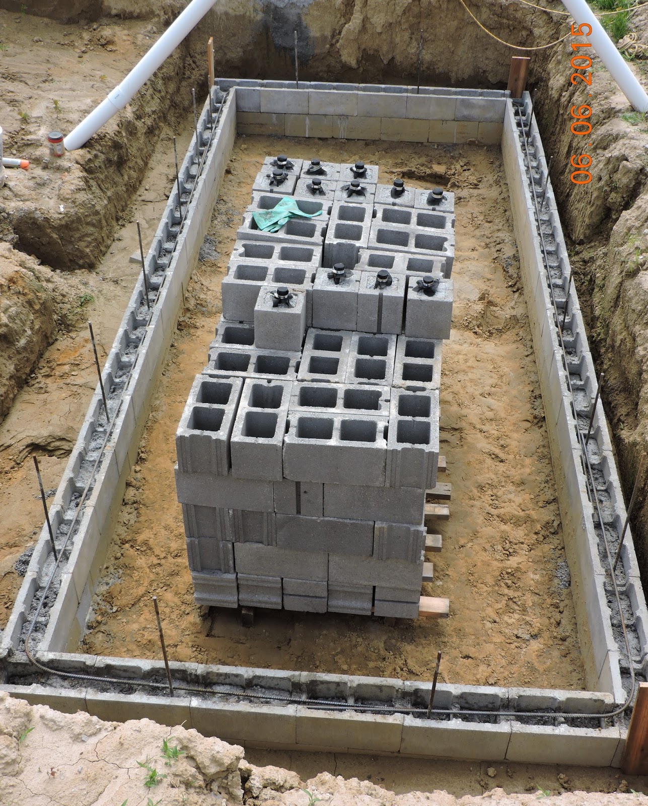
Since the collector is buried in the ground, the walls have to brace several feet of backfill. It could have been constructed with poured concrete on a poured footing resting on virgin soil, similar to a foundation wall.  In order to save money and to be able to design it as we went, I opted for dry-stacked concrete blocks resting on virgin soil and sand.  The first course
Bond beam course partially filled; horizontal rebar in place
was 4" x 8" x 16" partition concrete blocks  in order to have a smooth surface against the ground. The north wall was 12 courses high (about 8') -- one course higher than the final grade. The south wall could be 4 courses shorter than the north wall due to the slope of the hillside. The ends were stepped to reconcile the differences in height of the north and south walls. The walls were then capped with 2 x 10 pressure treated boards bedded in mortar and fastened with anchor bolts.  


The collector will need a fence to meet code.  The decision between mounting it on the top of the walls or setting it back a ways so as not to shade the collector will be made eventually after observing the solar gain on the finished collector. The fence will also have to be designed to keep small non-climbing critters out.  As far as deer are concerned, all we can do is pray that one doesn't jump in and land on the glass.
Friend Dave covering the rebar with more concrete; the
ramp above him was used to slide buckets of concrete
and cinder blocks into the pit.  The sprayer was used to.
moisten the blocks before adding concrete.

The tall north wall was reinforced horizontally with three courses of bond beam blocks filled with concrete and #4 re-bar -- one bond beam course near the bottom, another halfway up and the other near the top. The other three walls, since they were shorter, had only two bond beam courses. The cores of the corner blocks and the cores of about a half of the intervening blocks for all four walls were filled vertically with concrete, except, as explained below, the south wall had fewer unfilled cores.

Extending about a foot downward into the soil from the bottom of vertically-filled cores in all four walls were 3" Schedule 40 PVC pipes that were filled with concrete when the cores above them were filled.  They also held the lower end of the vertical re-bars that rested on 2" PVC pipe caps dropped into the 3" pipes upside down. The purpose of the caps was to keep the rebar from coming in contact with the soil to eliminate the problem with the steel rusting, expanding and cracking the concrete. The purpose of the 3" PVC extensions, well anchored in undisturbed soil, was to resist the lateral pressure of the backfill against the bottom of the wall.

Fiber Bonded Cement Parge
Both sides of the walls were parged (stuccoed) with fiber-bonded cement as is typical with dry-stacked cinder blocks, except for the south wall where there was not
Half blocks were turned on edge to provide entry holes
for the smooth conduits; other half blocks in all four walls
 contain pre-made weep holes ; the picture was made
 just before the top row of bond beam blocks and many of
 the cores were filled with concrete and rebar.
enough room between the blocks and the excavation in which to work.  To compensate for the lack of parging on the outside of this wall (the compression side of the wall) additional cores were filled vertically with concrete. I can live with this compromise because it is the shortest wall and, for strength of a dry-stacked wall, it is more important to parge the tension side. Parging of at least 1/16th of an inch thick on the compression side and 1/8th on the tension side in tandem with selective core-filling gives a much stronger wall than the typical mortared block wall -- actually strength that more nearly matches a monolithic concrete wall (Rob Roy, "Earth-
Closeup of a weep hole pre-made from a half block
 turned on edge; PVC pipe was concreted in and
 geo-textile fabric was added prior to dry stacking
Sheltered Houses", New Society Publishers, 2006, p.102).  The other three walls were parged on both sides which, in addition to strengthening them, also eliminates water penetration through the (un-mortared) gaps between blocks.


The integrity of the taller north wall was severely tested only a week or so after backfilling (without compaction) when, not one but two, concrete trucks parked on the backfill while pouring the footing for the north wall of the house. After the trucks left, the backfill was thoroughly compacted -- it had sunken by a foot and a half.

Weather Related Change
Unfortunately, heavy rains over a period of several weeks (global warming induced?) not only delayed construction but created more work.  The rains started after three courses of blocks were stacked. The run-off followed the gravel around the conduits from the huge area that was graded for the slab floor directly into the "pit" to deposit 8 - 12" of  silt in the
Two concrete trucks parked on the backfill for the collector
with no ill-effects on the DIY walls of the collector.  (Whew!)
over-dig surrounding the walls of the collector and on the floor inside the walls. This circumstance was a mixed blessing.  On the one hand, how better to get compacted backfill around the base of the wall? But, on the other hand, the parging could not be carried as far down on the wall as intended. Consequently, we filled with concrete all of the cores in the first course of conventional blocks as well as the first bond beam course. This change should more than compensate for not being able to start the parging at the bottom of the wall.


Managing the Water Problem During Construction and Beyond
It is a given that the collector, being in a pit, will collect water as well as sunlight.  A good thing happened unexpectedly during the excavation that solved the water problem. The excavation for the collector was deep enough to uncover near its center one of the French drains but, unfortunately, beyond where it had been perforated (details on perforation).  So I removed a 5' section of the exposed drain and substituted a new section that was copiously perforated and wrapped with the same geo-textile fabric used with the French drains originally.  The replacement was sorely tested during numerous hard rains in May and continuing through early August because, as mentioned above, most of the runoff from the house footprint followed the conduits into the excavation for the collector. After a rain, the house footprint dried out within three or four days but the pit not for a week or so.   However, without the serendipitous drain, water would have stood in the pit indefinitely because our wind-blown loess does not naturally drain as quickly as loamier soils.  

The record rainfall in June was slightly more than three times that of normal.  To eliminate some of the runoff that had been so readily finding the collector, I finally resorted to covering the footprint of the house
The house footprint, except for garage, was covered with
tarps; the soil, conduits and gravel behind house were
 covered with plastic
with huge tarps that I had found on Craigslist well in advance of starting construction, knowing that they would be useful in some manner later. Then, just before the remnants of tropical storm Bill reached us, I covered the north ends of the AGS conduits and the gravel around them with 6 mil plastic sheeting pinned down with 8" and 12" exterior spikes and further anchored with blocks and unused PVC pipes.  This arrangement kept most of the water on the surface instead of following the conduits into the collector (at least for a few weeks until UV rays caused the plastic to fail but enough time to get the collector finished).  I then hand-dug shallow trenches south of the tarps in order to channel the surface water away from the excavation. The system was immediately tested with 4" of rain in three days whereby the amount of water reaching the pit was limited and quickly siphoned away by the French drain. Such a trial run would seem to indicate that the serendipitous drain will keep the collector sufficiently dry in the future.

The ends of some of the corrugated pipes are visible while 
others are hidden by collapsed soil and gravel that was
undermined by runoff  following the conduit trenches.

Between now and when the time is right to finish the collector, presumably in about a year, the extra dirt that the water has deposited on the floor will have to be removed, the floor sloped towards the French drain and a few inches of white gravel added with landscaping fabric underneath.   Once the excavation for the conduits and the space around the collector have been backfilled, the slab floor for the house has been poured and the insulation/watershed umbrella has been installed, the only water inside the collector will be limited to whatever falls into the collector itself and should be easily handled by the French drain. 
Pat attaches a fitting to connect the last (of nine) corrugated
conduits to a Schedule 40 pipe running to the collector.
 Keith prepares the sand bed for the horizontal insulation under
 the pipe.  Two of the four pier forms have been installed over
 pre-poured footings and the vertical insulation is in place along
the west wall of the excavation.  The sand was subsequently
reconfigured to to cover the pipes uniformly to a depth of
 four inches.

The white gravel for the floor of the collector will be ideal for reflecting short wave length solar radiation and converting it into long wave length that cannot pass back through the glazing (greenhouse effect). The collector will be designed to funnel the resulting heat into the conduits where it will flow passively about 78' to daylight  (20' of smooth pipe between the collector and the house, 38 ' of corrugated pipe under the house and another +/- 20'  of smooth pipe behind the house).

With regard to plant growth inside the collector, the assumption is that, once the collector is finished, the temperature inside will be too hot for plant growth.  The use of landscaping fabric under the gravel may therefore be unnecessary, at least for the hottest part of the summer.  But maybe we will have created the perfect greenhouse and plants will be a big problem despite the fabric, in which case, more drastic and unwelcomed measures will be necessary -- only time will tell.

Foundation Footings over the AGS Conduits
Parging the south wall with fiber bonded cement.  Notice
the anchor bolts for the 2 x 10 pressure treated boards
 that will cap the top of the wall.
In hindsight, we should have trenched for the corrugated pipes well beyond the south wall of the house so that the footings and foundation wall would be resting on virgin soil.  As it was, the excavation that was necessary to uncover the corrugated pipes so they could be joined with the smooth conduits severely undermined the footings, foundation wall and the edge of the slab floor.  To make matters worse, rains caused soil and gravel around the pipes to collapse into the excavation (check out the sixth pic from the top).  As referenced in the second post, four concrete piers about 5 - 6' apart were inserted between conduits to support the footings and wall then the excavation around the piers, under the slab and for a ways in front of the house was backfilled with rock that was dropped from sufficient height to be 95% compacted. That part of the footing for the south wall of the house bridging across the excavation will be beefed up vertically with twice the amount of concrete and rebar since it is basically a beam supported by the rock and piers.

Insulation
In conjunction with installing the PVC pipes that bridge between the corrugated pipes and the collector, four sides of the excavation were insulated -- the floor, the north wall of the collector and the east and west walls.   One layer of two-inch thick extruded polyethylene insulation board was laid on the floor of the excavation over a thin layer of sand.   I considered using expanded polyethylene (Styrofoam) for a couple of reasons but opted for extruded with its 250 psi compressive strength since there will be 5 - 6' of backfill on top with vehicular traffic passing over during construction. The sides of the excavation were also insulated as was the outside of the north wall of the collector but, since these areas did not have to carry heavy loads, cheaper 150 psi was used..  Actually, the insulation for the north wall of the collector was mostly a freebie from the local farm and home store.  It was Styrofoam in big chunks that were easily carved up with table and handsaws. 

I decided to use extruded polyethylene for insulation with some trepidation after having run onto a YouTube posting showing water being rung from extruded poly which contradicts the claim of extruded polyethylene as to its low water absorption. (Water logging reduces R-value to near zero.)  Expanded poly is used universally in wet environments from insulated concrete forms to boat docks, so maybe it makes sense to use it subgrade and devise ways of protecting it from loading.  More on this subject in a subsequent post on the AGS insulation/watershed umbrella.

The primary reason for insulating the excavation at all is to prevent heat loss from the conduits to the soil in front of the house before it can reach the thermal mass under the
Backfilling with rock around the piers to help support the
footings under the front wall of the house.
house.  A secondary reason is
 to reduce heat loss from under the house when the AGS system mothballs for winter.  The insulation of the conduits will be complete when the insulation-watershed umbrella is installed below grade a couple of feet above the pipes.  If water saturation is indeed a problem with the extruded poly insulation, the umbrella should keep it dry enough to function anyhow.

Backfilling
Backfilling of the excavation was done in stages as soon as the collector walls were built, the rigid conduits were connected to the corrugated conduits and bedded in in sand, the insulation
Completing the backfill of the excavation over the AGS
conduits that were bedded in sand ahead of time.
was in place and the footings for the piers as well as the piers themselves were poured. Sand was used first to support the rigid pipes and cover them to a depth of about 4" to protect them from the rock and soil falling from the backhoe.  


First, clean rock was dropped in to provide a more compacted base for the footings, foundation wall and slab floor.   The rest of the excavation was filled with uncompacted dirt which should be sufficiently settled by the time the insulation/watershed umbrella is installed.


Air Flow
Presumably, we will be ready by next summer to finish the collector which will include building the framework to support  the glass. The south side of the framework, 18" in from the south wall, will comprise mostly air vents because the cross-sectional area of the vents will need to be considerably more than that of the cross-sectional area of the nine AGS conduits added together in order to be absolutely sure air flow through the conduits is not impeded by a lack of intake air. And the vents will require something like hardware cloth to keep critters out of the collector and conduits.

Monday, August 3, 2015

Odds 'N Ends - Lesson from a Tepee (Cont'd)

The first post on tepees covered many of their unique features such as shape, orientation, materials, smoke flap function, insect control and some of the Youngs' camping experiences in a tepee, including winter camping.  This post adds other interesting tepee factoids.

Tepee Poles
The plains Indians lived nowhere near good trees for poles and had to travel several
Lodgepole pines
hundred miles west to the Rockies to harvest lodgepole pines.  Consequently, poles were
cherished and lasted a long time.  The 14 poles supporting the cover were traditionally several feet taller than the cover while the two poles that moved the smoke flaps were shorter. Two of the oldest and most dispensable poles were used for the travois which meant that dragging them on the ground behind a horse wore them shorter.  So they were relegated to smoke flap poles.  I suspect the extra length for the other poles was intended to delay pole-cutting treks to the mountains as long as possible.  As the bottoms of the poles deteriorated from being in contact with the ground, the extra length allowed the poles to be shortened many times before having to be demoted to smoke flap duty or replaced entirely.

For a 20' tall tepee like those we had, the poles needed to be at least 24' long.  The unique thing about a long lodgepole is that the diameter at the tip is only slightly smaller than the diameter at the base -- only about 2 - 3" for tepees.  The minimal taper gives them the stiffness they need to carry the weight of the canvas despite being so slender.

Pitching the Tepee
If the squaws were responsible for pitching and striking the tepees, ever wonder how agile some of them must have been to shinny up the poles to tie and untie them at the top?  Didn't happen.  The three sturdiest poles are tied together flat on the ground then spread out and tilted into place to form a tripod.  The excess rope dangling from the top is more than long enough to touch the ground.   The other 11 poles are then laid into the forks of the first three in a very precise order.  After the poles are in place, the excess rope is wrapped from the ground around all of the poles and tied off to one of the tripod poles.

The cover is raised and secured just as easily.  It is laid on the ground around the periphery of the tepee with its midpoint directly opposite where the door will be.  Then the smoke flap poles are inserted into the pockets for them at the top of the smoke flaps and used to lift the cover into place.  It is subsequently draped around the poles towards the door then overlapped over the door and laced together with 1/4" thick sticks that fit in matching pairs of "button holes".  The nearest thing to climbing the squaws might have had to do was to secure a stick across the door opening on which to stand while lacing the cover together.

Doesn't It Rain In Around the Poles?
Yes, but not much. Most of the water runs down the underneath side of the poles to the ground unimpeded as long as the poles are smooth and there are no obstructions.  Consequently, the poles have to be debarked while they are green and the knots that are left where the limbs were have to be shaved smooth.  Moreover, the ropes that attach the liner to the poles cannot lie directly against the poles.  Instead, two small twigs are wedged under the rope to hold it away from the pole on the underneath side, providing a clear waterway to the ground.

As mentioned in a prior post, our first tepee was pitched in Illinois in the mid-70's.  Rather than having 16 lodgepole pine poles shipped from one of  the Rocky Mountain states, we used native trees with terrible results.  They were bulky, heavy, crooked, tapered too much and were difficult to get smooth enough to carry the water to the ground without drips.  We ended up shortening the poles to just above the liner and covering them with a god-awful metal lid from a hog feeder.  Ugly and insulting to tepee-ism.

After a couple of years of making do, we took the tepee to Colorado for a two-week camping vacation.  We arranged a head of time to pick up new lodgepoles near Aspen (which gave us an opportunity to tour the town overnight).  We then hauled the poles on the rack atop of our DIY trailer behind our 4-W drive International Scout to Crested Butte, a ski town that was the nearest civilization to our planned campsite at 11,000 feet. Interestingly, Aspen and Crested Butte are hiking distance apart as the crow flies but multiple hours apart by road because they are separated by the continental divide. One of the ski resort motels in Crested Butte stayed open during the summer so we touristed Crested Butte by evening and de-knotted our tepee poles with butcher knives on the motel parking lot by day.

Eventually, we did have a second set of poles shipped from Montana when the original set deteriorated after about 15 years.  The truck driver was amused by a bundle of "What?" that was more than half as long as his trailer.  As mentioned in a prior post, we took the cover home during the summer but we left the poles in place and unprotected.  Otherwise, a second set would not have been necessary

Isn't the Tepee Smokey?
Also as explained in detail in a prior post, the smoke from the campfire is at the mercy of wind direction and barometric pressure.  The relationship between the liner and the cover in conjunction with the smoke flaps limit the amount of smoke campers have to deal with -- much less actually than around a campfire in the open -- because the fire inside is controlled and predictable.  

There is no wind inside, so the heat of the fire causes the smoke to rise naturally whereby the air coming in between the liner and the cover picks it up and carries it out through the smoke flaps.  Make-up air for the fire enters in an intentional manner either below the door or through an opening around the door that is tailored in size to the amount of air needed for the fire -- much like opening and closing a stove damper.  

Okay, What Is the Lesson That the Tepee Teaches Us?
For some it may be a stretch but for me it is easy to see a parallel between the tepee and green building to the degree that both work with nature instead of against her. In my view, that characteristic goes a long way in defining sustainability.

Tuesday, July 28, 2015

Odds 'N Ends - Lesson from a Tepee

The tepee is such an unique and interesting shelter that it takes two posts to do it justice.Several visitors over the years said things like "Wow, this is cool space" or "I had no idea". Where I am going with this Odds 'N Ends piece is to draw a parallel between the tepee and green building with respect to working with nature instead of against her.  Also, I am betting that most readers have never given tepees much thought and might find the following information interesting.

My late wife, JoAnn, grew up in the country back when there was no indoor plumbing and, early on, electricity as well.  She was only too happy to enjoy the benefits of city living and was not terribly interested in camping, at least until the youngest of our four kids was potty trained ("I am not going to wash diapers in a bucket"). When it was time to begin camping, I researched the subject thoroughly and decided that the tepee was by far the best choice for semi-permanent camping.


Subsequently, our family wore out two tepees between the time our youngest kids were grade schoolers and our grandkids started noticing girls.  We treated them as "permanent" shelters by leaving them in place from year to year rather than moving them around like folks who attend rendezvous on weekends.  The only breaks in this routine in Illinois were for a two week tepee vacation just below the treeline in the Colorado mountains and two years in the north woods of Michigan.

A good downloaded image; the only thing that is
missing are the tethers for the smokeflaps
Shape
Ever notice the shape of a tepee?  It's conical so that it funnels smoke up and out during winter and sucks heat out during summer.  It also restricts the amount of unusable space above the living area that must be heated and cooled.  And it allows the poles to be thinner and lighter because a cone (triangle) is the strongest of all configurations. Our tepees were 20' in diameter and 20' tall, fitting the definition of a cone.  There was plenty of room for five army cots around the periphery for seating and sleeping. The middle was used for cooking and clean up with the fire-pit situated between that area and the door.

Orientation
A tepee always faces east so as to turn its back against the prevailing west winds (northern hemisphere) and to orient the smoke flaps (located just above the door) so that they draw the smoke out most efficiently.

Cover and Liner
The size of the original tepee was limited by the weight of the buffalo skins covering it.  However, when canvas was as close as the next raid on a prairie schooner wagon train, canvas became the cover of choice and allowed tepees to grow.

Hugging the inside of the tepee poles is a liner that runs from about eye level to the ground then turns under against the ground on the inside (notice in the picture how the tepee is darker near the bottom due to the liner blocking the light from the fire).   While the liner is sealed against the ground, the cover is intentionally held off the ground several inches.  This relationship between the cover and the liner creates a natural updraft that carries the smoke out through the smoke flaps.  In summer when cooking is typically done outside, the liner is also raised above the ground in order to improve ventilation.

Smoke Flaps
The smoke flaps are long rectangles projecting a foot or more from the cover above the door, the outside edges of which have rope tethers at the bottom and pockets at the top to receive the ends of two poles.  When the wind is from the north, the ropes and poles are used to tilt the flaps towards the south, much like a person would manipulate his/her coat collar or hoodie against a side wind.  When the wind is from the south, the flaps are tipped in the other direction.  When it blows from the west, the flaps extend due eastward, similar to their position in the photo.   When it rains, the degree of tipping is exaggerated so that raindrops are intercepted by the flaps instead falling on the floor of the tepee or on the fire-pit that lies immediately below the flaps.

When the wind is out of the east, which, fortunately, is relatively rare except just ahead of a front bringing rain or snow, the flaps are tipped like it was raining. Even then, an east wind and falling barometer can make a tepee pretty smokey.  Not only does the smoke have trouble bucking the wind, low pressure keeps the smoke from rising.

Insect Control Without Screens
Insects are repelled by smoke.  Having a fire inside unequivocally precludes an insect problem.  We found during the two years we camped in the north woods of Michigan that even the pesky no-seeums stayed outside at night.   Supposedly, in summer when the fire moves outside, the tepee retains the scent of smoke sufficiently to discourage insects.  However, we did not test this postulate because we disliked summer camping and the hot, humid weather degraded the canvas.  We made it a practice to camp from early September (beginning of squirrel season in Illinois) until early May (end of morel mushroom season) then remove the canvas liner and cover to storage for the summer.

Cold Weather Camping
In mid-life, I went to graduate school.  A patient invited us to move our tepee to his summer compound in northern Michigan during our two-year stay in Ann Arbor.  We had regularly camped in the tepee in winter in Illinois so the second winter in Michigan, we decided to try winter camping there.  The temperature hovered at 15 degrees below zero at night and the snow cover was over two feet deep.  We finally got settled in after digging out the tepee and schlepping our groceries and gear several hundred feet on cross-country skies.  The tepee was surprising comfortable after the fire had burned for a few hours to the extent that we could remove our coats and be comfortable in sweaters.  It did however get cold enough by morning to freeze our eggs despite keeping the fire lit by tossing firewood from under my cot into the fire-pit several times during the night.  By mid-morning we were back to wearing sweaters.  

Tepees Were Better Than Log Cabins

I was not surprised to read years ago that the Native Americans were more comfortable in their tepees than the settlers were in their log cabins, mostly because the shape and size of cabins make them hard to heat.  As the weather grew colder, the Indians untied the bottom of the  liner from the poles and let it hang straight down so as to reduce the area that needed to be heated.  In some cases, a canvas ceiling called an "ozan" was hung horizontally above the living space even with the top of the liner to create a lean-to effect to trap and hold more heat from the fire.  We actually made and used an ozan for winter camping in Illinois but without hanging the liner straight down.  Even then, it made the tepee surprisingly more comfortable on cold nights.

Monday, July 20, 2015

Construction - AGS System for Passive Solar Heating and Air Conditioning - Cont'd

This is the second of three posts on the actual design and installation of the AGS system. The first post dealt with the conduits that distribute solar energy through the thermal mass under and surrounding the house.  This post focuses on the second important element of the system -- the solar collector.  Another element is the insulation/watershed umbrella.  I will describe it in detail once it is installed.  Its installation will fall sometime between wrapping up the concrete work and beginning wood construction -- possibly as soon as a couple of months out, weather permitting.

(Reminder: click on any photo below to enlarge it for closer inspection.)

Depth of the Solar Collector
My initial concept of the solar collector was not well thought through.  I simply failed to realize that the 15 degree slope in front of the house was too shallow for the floor of the collector to be 9' below the floor level of the house and still be even close to the height of the surrounding grade.  Fortunately, having to bury the collector does not significantly limit solar gain because the summer sun orbits so high in the sky that, even when the glass is 4 - 6' below the surrounding grade, it will shine on the collector a sufficient number of hours each day. This is in contrast to a typical winter passive solar system for which the glazing would have to be closer to the surface in order to catch the low-angle winter sun,.

Size of the Solar Collector
Several years ago, we visited near Spokane an AGS-conditioned straw bale house having 3' x 20' glazing for its collector in a climate with a third more heating degree days and considerably less available summer sun than we have here.  Therefore, I was confident that the tempered glass panes we found for free on Craigslist -- enough for a 4' x 18' collector -- would do the job.  I could easily conceptualize the 18' dimension but not the 4' dimension. Once I determined the angle that put the glass perpendicular to the summer sun, I realized how flat the glass would be and how big the shell for the collector would have to be.  Unfortunately, I didn't do the math before the excavation for the collector was done and had to have the contractor dig some more and, even then, the pit was too small in the N-S direction for easy wall construction of the south wall of the collector.  In the second photo below, notice the proximity of the excavation to the south (right) wall of the shell for the collector.

Excavation Between the House and the Collector
As detailed in the first post , the nine corrugated conduits begin at the future front wall of the house, fan out under the house to connect with smooth pipes in the backfill behind the
View showing the extent of the excavation for the smooth
pipes; a few of the corrugated pipes can be seen at the
base of the drop-off; the rest have been buried by gravel
and soil washing out of the conduit trenches; the
tripod at the right supported a rope and pulley for swinging
heavy items into the pit while working alone
house that run to daylight. 
 At the front wall, they are bunched together so as to be lined up for a run to the collector in parallel using smooth PVC pipes. Rather than trenching for the smooth pipes individually, the run to the collector was opened up completely with enough depth that the smooth pipes will increase slightly the 3 degree inclination that was already built into the corrugated pipes. (The inclination is critical for the heated air from the collector to pass passively through the conduits and exit some 70' later behind the house).

The excavation between the house and the collector was not inconsequential, being over 20' square and sloping from 5' deep at the corrugated pipes to 6' at the collector.  It also undermined the front wall of the house to such an extent that five piers on individual footings resting on virgin soil in the floor of the excavation were installed before backfilling the excavation. The footing for the foundation will be doubled in thickness (height) since it spans the excavation as a beam supported jointly by the piers and rock backfill.

Excavation for the Collector
The excavation for the collector was not inconsequential as well. The pit for the collector was dug 22' in the E-W direction and 10' in the N-S direction.  As already mentioned, it would have been better had it been 12' north to south and 24 feet E-W to give more room for dry-stacking the block walls. The original depth for the excavation at the collector was approximately 9' below the floor level of the house. The conduits will eventually penetrate the wall of  the collector about 3' above the floor of the excavation and the north wall of the collector will need to be at least 6' higher than the conduits as a retaining wall for restoration of the original slope of the ground in front of the house. The the other three walls will need to be more like 3' higher than the collector.  The disparity in wall heights will be handled with natural rock retaining walls extending outward from both ends of the north wall.

Unfortunately, I did not photograph the pit before installing the first three courses of blocks. So this picture, taken after the first bond beam course was partially filled with concrete, is a little premature for this post but is included to give perspective on the size of the excavation for the collector.  The rigid AGS conduits (smooth pipes) will connect with the collector on the north side (left in the photo).

Glazing
The link "Duration of Sunlight for 2015" for Collinsville, IL, shows almost identical "solar isolation" (maximum amount of available sunlight) for the weeks leading up to June 21 versus the weeks following. The website does not account for cloudy weather so I am betting there are more clouds interfering with solar collection during the rainy weeks preceding June 21 than during the dry summer weeks following it. Accordingly, I decided to use the sun angle for July 10 instead of June 21, which was easy to do by going online to Solar Position Calculator.  Our sun angle for July 10 is a steep 74 degrees off horizontal. The most efficient angle for the glass is one that is perpendicular to 74 degrees  or 16 degrees off horizontal.  

 "April showers bring May flowers" seems be an oxymoron anymore.  Our Spring rains seem to come later and later to the extent that this year our rainfall for June was three times normal and the rain during July is running above normal as well. Maybe, in the future as the weather changes in response to global warming, a July 10 target will prove to be too early for capturing the most sunshine .  Although we are not doing it, it might make sense to consider making the tilt of the glass adjustable.

The width of the four panes of glass is 4' and their total length is 18'. The perpendicular angle to the sun angle is close enough to horizontal that the glazing for the collector will cover 80% of the total area inside the concrete shell.  There will be only 18" of access space along the south wall for maintenance, such as cleaning the glass and clearing out leaves, and to allow an unobstructed flow of air into the front of the collector.  The glazing for the collector is quarter inch tempered glass which may be not be strong enough, at such a flat angle, to withstand the kind of hail storms we see frequently here in the Midwest.  If not, it may have to be replaced with 3/8 inch tempered or a plastic/fiberglass material of some kind.

Clear Glass or Translucent?
When sunlight passing through glass strikes various objects and surfaces behind the glass, the short wavelength energy is converted into long wavelength energy that is incapable of passing back through the glass -- hence, the "greenhouse effect". Darker objects tend to absorb the energy and lighter objects tend to reflect the energy.  For our AGS system, we want as much energy as possible not to be absorbed and bound up in the collector but to be reflected and encouraged to leave through the conduits.  With our clear glass panes, a white gravel floor for the collector that reflects rather than absorbs will be best even though some of the energy will not be diffused and will be lost back through the glass.

However, the best of all worlds would be translucent glass instead of clear glass.  To paraphrase one authority, "translucent glass is transparent to the incoming wavelength and opaque to the outgoing wavelength".  The glass itself diffuses the incoming energy and traps it all rather than some going back through the glass.  I suppose this is why old-fashioned greenhouses with real glass roofs usually have what looks like whitewash on the glass and why untinted translucent fiberglass is recommended over clear materials for homeowner greenhouses.  We will be using this principal for the second story windows of the house as will be discussed in a future post.

Update - Summer 2016
When this post was written, I thought I had a grasp on how the solar collector should work. Since then, a scientist friend has helped me understand the design from a thermodynamic perspective which is much different than what I wrote above.  In the near future, I will be devoting an entire post to the design of the collector.  Stay turned.

Sunday, July 19, 2015

Timeline - Alternative Certifications to LEED


The quest for some sort of sustainability recognition for our project started with the assumption that LEED (Leadership in Energy and Enviromental Design) certification
would be attainable and affordable.  As discussed in the first post on certification, the LEED fee of up to $2,000 turns out not fit our budget and certifiers seem to be uniformly disinterested in residential construction.  This post shares some of the information gathered while searching for an alternative to LEED. Most of it comes either from Johnston and Gibson's book, "Toward a Zero Energy Home - a Complete Guide to Energy Self-Sufficiency at Home”, or from Stan Clark (Advance Green Consulting, LLC), a local energy consultant that I trolled onto while looking for a LEED certifier.

A big positive for LEED is that it rates sustainability from conception to completion. The other green ratings/certifications, except, to some extent, NAHB, focus on energy conservation of a built house.  In addition to the requirements listed below for other certifications, LEED is unique in requiring the following:
  • Site selection:  In-fill and urban instead of suburban, exurban and rural
  • Proximity to infrastructure:  Schools, shopping, medical care, entertainment
  • Site stewardship during construction:  Erosion control, minimal site disturbance
  • Green building practices:  Off-site fabrication, FSC-certified lumber, materials with low embodied energy and salvageable end-life, recycled materials, advanced framing, minimal construction waste
HERS Index (Home Energy Rating System)
  • HERS is the most economical alternative to LEED -- $700 - 800 -- but still has high kudos in the green building industry
  • Rating is based upon a hypothetical code-compliant "conventional home" (a production home as opposed to a highly detailed custom home); the conventional home is given a HERS SCORE of 100 against which a subject home is compared; a score of 20 or below is excellent and rare
  • Certification includes a plan evaluation and computer modeling
  • Periodic inspections by a certifier are done during construction to monitor and test energy efficiency procedures, both before and after the insulation is installed
  • Inspections include blower door testing and HVAC duct pressure testing
  • The process culminates in a report and certificate
Energy Star Version 3
  • $850 - 1000
  • More stringent guidelines but higher recognition
  • Plan evaluation and computer modeling
  • Inspections for insulation and air infiltration control
  • Blower door testing, HVAC duct pressure testing
  • Report and certificate; certificate sent to a federal registry
The interesting aspect of the Energy Star approach is that a project is rated against a hypothetical "Benchmark Home".  According to Stan, our project may not be Energy Star certifiable because it is too non-standard.

NAHB Green Build Standards (National Association of Home Builders)
  • $1400-1500 which includes the price of submission to NAHB national registry
  • Many guidelines regarding sustainable practices during construction (similar to LEED requirements)
  • More compliance inspections than for HERS and Energy Star
Stan Clark, who's certified in HERS, Energy Star and NAHB, says he will be able to obtain certification for our project but it will require some creativity on his part.  Isn't it ironic that a project can be potentially so out-of-the-box energy efficient and sustainable as to defy certification?

Friday, July 10, 2015

Timeline - Certification - Is LEED worth chasing?


Why Certification At All?
We field this question often and those asking are usually professionals such as contractors, architects, engineers and consultants who are not yet involved in green building. They contend that the energy performance of the house will speak for itself through utilities bills.  So why pay for a certification?  One green building contractor said that we should "use the money spent on LEED certification for something nice like marble counter tops" and go with a less expensive certification program.  Several others in the green building movement voiced the same opinion.  As for the question, "Why certification at all?",  we feel that certification fosters discipline and presents challenges that we might not meet otherwise.  Also we plan to make our home available as a demonstration site for which some kind of certification will lend authenticity. 

LEED 
In the beginning, I (more than Dorothy) was determined to go after the highest LEED certification possible and I was not willing to abandon this goal even after receiving input from the professionals.  Since LEED is a function of the Green Building Council, I downloaded from their website a document titled "LEED for Homes -- Frequently Asked Questions".  From it I got the impression that their pilot program for homes ended in 2006 and home certification would soon become commonplace despite the anticipated fee of $500 to 2,000 per dwelling.

However, my enthusiasm soon waned.  In the first place, it seems like LEED certifiers are still interested in commercial projects, not residences.  Among the list of certified buildings on the local Green Building Council website in 2012, there were only a few certified residences and most of those were Habitat for Humanity Homes. I left messages on the local GBC website and tried to contact certifiers listed for our area on the national GBC website as well as on the website given in the document that I downloaded -- all to no avail.  I tried networking through the building trades to find a certifier.  I did a presentation before the local chapter of the GBC during which I specifically asked for help finding a certifier.  Afterwards, two architects said they would see what they could do to find someone but I heard nothing from them.  It has been one frustrating blind alley after another.  But maybe it is just as well.

Cost of Certification
Realistically, LEED certification is too expensive for our budget and the fee probably would not pay for itself through any bump in resale value anytime soon, as much as anything because the public will not be sufficiently educated on sustainability for who knows how long.  If this is the case, the only justification for chasing LEED would be for non-financial reasons such as ego gratification and recognition.  Personal kudos are not our goal.

Early Adopters
Recognition in itself might not be all bad, though.  I have heard that early adopters of new technology must reach 20% of the population before mainstream even notices.  The number is probably bogus but the concept is not.  I believe that we early adopters should do whatever we can to popularize sustainability and, in that context, any recognition that comes with certification is probably a good thing. 

Alternatives to LEED
In my next post, I will discuss three other certifications, any one of which probably makes more sense for individual residences with a reasonable budget than does LEED.

Saturday, June 27, 2015

Construction - AGS System for Passive Solar Heating and Air Conditioning

This post is the first of three on the design and installation of the AGS system.  It focuses on the conduits that carry the heat from the summer sun to the thermal mass under and around the house.  The other posts will be forthcoming as soon as the associated installations have been done.  One will cover the design for the solar collector and the excavations necessary to get it installed.  The last will discuss the construction of the shell for the collector, joining the conduits to the collector, insulating and backfilling the excavations.

AGS Design Review
The design of the Annualized GeoSolar system has been detailed in earlier posts (first postsecond post, third post).  In a nutshell, the heat distribution system itself has two components -- a solar collector for harvesting the heat from the summer sun and a series of conduits for conveying the heat from the collector to the soil under and adjacent to the house for storage.  Another important element is the insulation/watershed umbrella extending +/-20' outward from the house about two feet below grade so as to insulate and keep dry a thermal mass larger than the footprint of the house.  The necessity for dry soil is covered in the three posts cited above and more recently in one of the posts on French drains.  The construction of the umbrella will be detailed later after it is installed, which will take place after all of the concrete work is done and before wall construction begins.

Conduit Configuration
The conduits comprise two types of 4" pipe -- rigid smooth-walled Schedule 40 PVC and flexible un-perforated corrugated drain pipe.  The smooth pipes extend from the collector to just under the front foundation where they are joined to the corrugated pipes then again in back of the house between the corrugated pipes and daylight above the north grade which will be nearly two-stories high. The corrugated pipes are limited to the area under the slab floor.  

The heavy-duty smooth pipes serve two functions -- to withstand the weight of 8 - 14' of backfill and their smooth walls should expedite the flow of heated air from the collector. The corrugated pipes maximize heat transfer from the conduits to the soil by creating air turbulence. They can be utilized for this purpose because the weight of backfill is rendered moot by filling the trenches with gravel and pouring a concrete floor over them.

Designing the diameter, number, depth and inclination of the pipes was an educated guess on my part after reading the article describing AGS (Don Stephens paper) and visiting one of the houses he designed near Spokane (the Mica Peak residence mentioned in the paper) and research on earth homes.  In our iteration, nine conduits were installed which means they are about 10' apart after flaring out under the floor. As for depth, they leave the collector 6' below floor level, pass under the front foundation at 5' below floor level, pass under the back wall of the house 3' below floor level and run to daylight behind the house at a 45 degree angle.  Except for the latter, the inclination is about 3 degrees above horizontal which should be enough slope for passive convection of the heated air but not so much that the flow rate is too fast for efficient heat transfer to the soil.

The decision on the diameter of the pipes was based primarily on a good book on earth sheltering that I have since lost track of and on Hiat's book, "Passive Annual Heat Storage".  Before reading them, it seemed reasonable to me that the larger the pipe the more heat transferred to the soil, so my early thinking was to use at least 6" pipes. However, it turns out that a large pipe with a given internal volume has less external surface and therefore, as a conduit, less contact with the earth than several small pipes whose combined internal volume equals that of the large pipe. The situation is analogous to human body types.  Compared to heavier people (endomorphs), skinny people (ectomorphs) typically tolerate summer heat better and tend to chill more in cold weather because they have a high ratio of skin to body mass and therefore more surface area for heat transfer.  I also reasoned that going smaller than 4" might not suck the heated air out of the collector fast enough to keep the collector from overheating unless the number of pipes was increased beyond reason.

Installing the Conduits
Installing the conduits was a cakewalk compared to installing the French drains.  Our
Installation of the corrugated pipes
contractor, Brian Hayes, brought in an industrial-strength trencher.  As soon as he dug a trench we dropped in the corrugated pipe, connected a smooth pipe to it at the north end, backfilled to within a foot or so of floor level with man-made pea gravel then backfilled to grade with soil.  Most of the soil will be removed during the final grading for 4" of rock sub-base and 4" of concrete.


Solar Chimney Discarded
The original design called for bringing all nine conduits to daylight at the north end via a solar chimney.  However, during installation, I decided to dispense with the solar chimney and run the conduits to daylight separately.  The change was driven by several things but mostly by my fear that the system might prove so efficient that the house would overheat. Stephens mentioned this concern in his paper and suggested incorporating thermometers
AGS conduits headed towards daylight; trenches filled
and the site graded for the sub-base and slab
in the soil below and behind the house in order to monitor the heat uptake and make corrections (presumably by closing some of the conduits at the collector). He suggested it might take several years in any case for the thermal mass to reach a stable year-round floating temperature so overheating would not be a problem for at least a couple of years for our project.  I decided that it made more sense to leave the conduits separated so that some could be capped for all or part of a summer following a winter with an overheating problem rather than trying to manage the problem at the collector end.  And it would be possible to reverse engineer a chimney later if proven necessary.

The other reason for keeping the conduits isolated was to eliminate the cost  and complexity of tying the conduits together and leading them into the solar chimney.