Sunday, April 23, 2017

Design - Vapor Barriers and air barriers

There are myriad materials marketed for controlling the flow of moisture and air through wall and ceiling assemblies.  However, it doesn't take much research to become confused about which to use where.  For example, the nearby map shows that, for our lower Midwest climate zone, we need an interior vapor barrier.  As we will see, this would be an unwise choice. When step-son, Keith, and I were building his house in a nearby county, even the building inspector was sufficiently ambivalent to accept the wall construction with or without a polyethylene sheet plastic vapor barrier.


This post is limited to those materials used on the inside of assemblies. The next post will tackle those used exteriorly. Furthermore, this post emphasizes vapor barriers for wall and ceiling assemblies while the next post completes the story by discussing air barriers.

The Problem
Anyone who is involved with building a house would do well to read "Understanding Vapor Barriers" by Joseph Lstiburek on which the following discussion is based.  He says that "Vapor barriers are...a cold climate artifact that have diffused into other climates more from ignorance than need. The history of barriers itself is a story based more on personalities than physics.....It is frightening indeed that construction practices can be so dramatically influenced by so little research...  Incorrect use of vapor barriers is leading to an increase in moisture related problems. Vapor barriers were originally intended to prevent assemblies from getting wet. However, they often prevent assemblies from drying. Vapor barriers installed on the interior of (wall or ceiling) assemblies prevent assemblies from drying inward.  This can be a problem in any air-conditioned enclosure. This can be problem in any below grade space.  This can be a problem when there is also a vapor barrier on the exterior.  This can be a problem where brick is installed over building paper and vapor permeable sheathing."

Simplified Terminology
Lstiburek proposes simplifying terminology.  He suggests that all of the materials used in wall and ceiling cavities that are capable of influencing the behavior of moisture vapor, such as house wraps, polyethylene sheeting, felt paper, OSB, plywood, foam insulation board with or without foil backing, drywall, latex paint, vinyl wallpaper and all cladding materials should be called "vapor retarders" because they all have the capacity of retarding the movement of water by vapor diffusion.  Vapor retarders should then be sub-classified into four groups according to the rate at which vapor diffuses through them as measured by their vapor permanence or "perm" as follows:

  • Class I Vapor Retarder:        0.1 perm or less
  • Class II Vapor Retarder:       Between 0.1 and 1.0 perms
  • Class III Vapor Retarder:      Between  1.0 and 10 perms

Then Lstiburek goes on to categorize materials generically into four groups based upon the above three classes as follows:

  • Vapor impermeable:                Class I Vapor Retarder       (vapor barrier)
  • Vapor semi-impermeable:        Class II Vapor Retarder      (vapor retarder)
  • Vapor semi-permeable:            Class III Vapor Retarder    (vapor retarder)
  • Vapor permeable:                    Greater than 10 perms
Air moves through wall and ceiling assemblies due to differences in air pressure and contains varying amounts of water in the form of vapor.  All of the materials listed below as vapor retarders have some capacity for blocking air movement and, in so doing, might be called "air barriers".  

Examples of Vapor Retarders
The following list comes from Energy.gov:
  • Class I:  Glass, metal, polyethylene sheeting, rubber membrane
  • Class II:  Unfaced extruded (XPS) or expanded polystyrene (EPS), 30# felt (asphalt coated paper), plywood, bitumen coated kraft paper
  • Class III:  Gypsum board, unfaced fiberglass insulation, board lumber, concrete block, brick, 15# felt (asphalt coated paper), house wrap
Choosing a Vapor Barrier
Lstiburek is quite clear as to best practices for choosing vapor barriers  Paraphrased from his work, they are as follows:
  • Avoid using vapor barriers where vapor retarders will suffice; avoid vapor retarders where vapor permeable materials will work; thereby "encouraging drying mechanisms over wetting prevention mechanisms
  • Avoid vapor barriers on both sides of an assembly so as not to block drying in at least one direction
  • Avoid installing on the interior of air conditioned space such vapor barriers as polyethylene sheeting, foil faced batt insulation and reflective radiant barrier foil
  • Avoid vinyl wallpaper on the interior of air conditioned spaces
Interior Vapor Barriers
A reasoned summary for when to use an internal vapor barrier like polyethylene sheeting is found in Green Builder and reproduced verbatim below:
  • Most buildings don't need polyethylene anywhere, except directly under the concrete slab or on a crawl space floor.
  • The main reason to install an interior vapor retarder is to keep a building inspector happy.
  • If a building inspector wants you to install a layer of interior polyethylene on a wall or ceiling, see if you can convince the inspector to accept a layer of vapor retarder paint or a "smart" retarder (for example, MemBrain or Intello-Plus) instead.
  • Although most walls and ceilings don't need an interior vapor barrier, it's always a good idea to include an interior air barrier.  Air leakage is far more likely to lead to problems than vapor diffusion (the italics are mine).
Both Lstiburek and Energy.gov say that drywall with latex paint on it, when installed
correctly, forms an adequate semipermeable vapor retarder for most of the US. As we sit at the junction of the mixed-humid and hot-humid zones depicted on the above map, this is obviously the best option for our project as well.  The only caveats that make our project different is that (a) we will not have conventional air conditioning for cooling and humidity control as would be expected for our area and (b) our earth sheltered design means our living space is partially below grade.  However, the energy recovery ventilator that we have planned should adequately replace air conditioning for humidity control and the earth contact walls will be not be in contact with moisture because of the French drains and the insulation/watershed umbrella. And the earth contact walls will not be subject to sweating because the earth behind them will be warmed by the AGS system (for info on AGS, click on "Featured Post" in the column to the left).

Vapor Control Varies According to Climate and Assembly Components
Despite the above advice for avoiding interior vapor barriers, there is no universal solution to vapor control for all situations.  Lstiburek's paper discusses various scenarios for exterior wall assemblies and specifies the best climate zone(s) for each (not only for zones depicted by the map above, but for severe cold climates further north as well).  In northern climates, for instance, the best practice is in fact to use an interior vapor barrier.  But, in another paper on air barriers, he warns against using them even in cold climates for air conditioned spaces.

Even though the primary function of air barriers is to limit air infiltration and exfiltration, they are also vapor retarders in that they control the movement of moisture-laden air through an assembly -- as we shall see in a subsequent post.

In the meanwhile, I will devote the next post to the newly-built cathedral ceiling so as to be able to reference it later for the follow-up post on air barriers.

Thursday, March 9, 2017

Design - Maximizing Passive Solar Gain (Cont'd yet some more) - Supplemental Heat, Thermal Environment and Exterior Colors

This is the fourth and last post on passive solar design.  The first post was an overview and ended with a list of design considerations.  The second post  discussed three of the considerations:  the location of the building, the room arrangement within the building and a protected entry to the building.  The third post delt with windows, thermal mass and surface colors.  Here we wrap up the series with supplemental heat for passive solar structures and the thermal environment.  Again I am relying heavily upon Mazria's definitive text as background and our project as an example.

Supplemental Heat
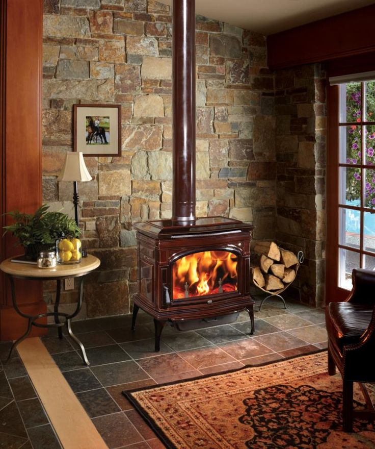
Wood burning stove
Only in places like southern California with mild winter temperatures and lots of sunshine is it possible to forego supplemental heating. According to one study, the annul percentage of heating provided by passive solar is closely associated with latitude and somewhat less with heating degree days. The percentage of heating that can be expected from passive solar ranges from 31.9% in Ottawa, Canada (45.3 degrees latitude and 8,838 heating degree days) to 60.2% for NYC (40.6 and 5,254) to 80.8% for Ft  Worth, TX (32.8 and 2,467).

The literature suggests that, for passive solar purists, wood-, corn- or wood chip-burning stoves and masonry heaters are commonly used to raise the ambient temperature a few degrees to a comfortable level, particularly in earth sheltered structures.  My guess is that most conventional homes embracing passive solar have conventional heating and air conditioning but down-sized to fit their passive solar capabilities.
Masonry heater

What makes Annualized GeoSolar conditioning (AGS) a significant upgrade from classic passive solar is that it maintains the same comfortable year- round temperatures that conventional HVAC systems provide.  (For details on AGS, click on "Featured Post" in the left column.)  And it does so by first increasing the size of the thermal mass then using the summer sun to heat it.  According to Hiat and Stephens, it takes a couple of years of solar input to reach the desired room temperature, during which auxiliary heat will probably be necessary.  Accordingly, we plan to use wall- or ceiling-mounted infrared heaters in tandem with wintertime passive solar as our secondary heat sources for the first couple of winters while the AGS system is heating the thermal mass. 

Eventually, passive solar alone should be sufficient to supplement the AGS system except possibly on below-zero cloudy days.  Then we will resort to infrared heaters.  Also not to be forgotten is the heat generated by people living in a structure.  The amount of waste heat from cooking, lighting, water heating and from human bodies is not inconsequential.  In fact, there are case studies in the literature in which waste heat provides half of the necessary supplemental heat for well-insulated passive solar installations.

Thermal Environment
Mazria discusses something that I have not seen in the other sources with which I am familiar -- what he calls the "thermal environment".  The topic is somewhat hard to grasp at first, much less explain, but here's a go at it.

There is a relationship between the air temperature and something called the mean radiant temperature (mrt) which is the average temperature of all of the surrounding surfaces.  Both mrt and air temperature influence the feeling of comfort but not equally.  Mrt has a 40% greater impact on comfort than air temperature which means that, for the same feeling of comfort, the air temperature can be reduced by 1.4 degrees for each degree mrt is raised.  The following examples come from a chart in Mazria (p. 64)

  • Mrt of 65 degrees means the air temp has to be 77 degrees for a comfortable feeling of 70 degrees
  • Mrt of 70 degrees means the air temp can be 70 degrees for a 70 degree comfort level
  • Mrt of 75 degrees means the air temp can be 63 degrees for a 70 degree comfort level
  • Mrt of 80 degrees means the air temp can be 56 degrees for a 70 degree comfort level
But how does all of this relate to passive solar?  Many things contribute to the mrt, or average temperature of all of the surrounding surfaces, but thermal mass -- the concrete floor and walls and, for the AGS system, the soil -- is by far the most important contributor. Once the mass reaches and maintains a constant temperature of say 75 degrees, the air temperature at night or on a cloudy day can drop to 63 degrees but it still feels like 70 degrees in the space, whereas in structures without thermal mass, a 63 degree air temperature feels like 63 degrees (or chillier due to air currents). However, if the thermal mass in contact with earth or exterior environment is not sufficiently insulated, the mrt might be so low that an inordinate amount of sunshine and supplemental heat would be needed for comfort.  This was one of the problems with older earth sheltered homes.

Ideally, the beginning of the heating season finds the temperature of the thermal mass already at a comfortable level naturally or due to air conditioning.  Then, the combination of solar gain, supplemental heat and waste heat maintains or increases the temperature such that swings in room air temperature are modulated within an acceptable comfort range.  Studies have shown that lower air temperatures are more invigorating and that one's ability to think and work improves when one feels warm in air temperatures below 70 degrees (Mazria) therefore the mrt of the space needs to be higher than 70 degrees.  A feeling of comfort is also enhanced by warm floors and the lack of air movement that occurs in most homes when a difference in floor and ceiling temperatures causes air currents -- from ceiling to floor and back.

Exterior Colors
Dark colors absorb more sun energy than light colors so the color selection for exterior surfaces of a passive solar home might vary with climate.  Up north, darker colors could be a good balance between heating assistance in winter without impacting cooling in summer.  In temperate and warm climates, light colors can be used to reflect solar energy as part of the thermal barrier for the envelope.  Radiant barriers can also be used in the attic to intercept solar energy before it has a chance to challenge the insulation. 

Our Project 
At a latitude of 39 degrees and heating degree days of just south of 5,000, we have the potential for getting around 65% of our heating from passive solar during the winter. However, we consider this option a bonus.  The AGS system will meet all of our conditioning needs because of the design of the thermal mass :  (a) it is considerably enlarged, (b) it is well insulated and (c) most importantly, it is heated from the earth side by the heat from the summer sun instead of from the house side from solar gain through the windows.  Our goal is a mrt that gives an average comfort level of 74 degrees year-round with the expectation that the mrt might drop a couple of degrees by the end of the winter and rise by a couple of degrees by the end of summer. 

Once we get past needing supplemental heat (2-3 years), it remains to be seen whether the combination of AGS, wintertime passive solar and waste heat produces more heat than we need. Already, we are optimistic enough to postpone thermal shades until the need for them is apparent. And we are prepared to mothball some of the AGS conduits should there be overheating from the summer sun.  Too much passive solar heat?  What wonderful problem to ponder.

As to exterior colors, our plan is to use white cladding and light colored roofing.  As explained in a prior post, we will have a well-ventilated "mini-attic" between the cathedral ceilings and the roof itself.  The sheathing to support the roofing will be OSB with foil backing as a radiant barrier to keep the roof cooler in summer.

Saturday, February 25, 2017

Design - Maximizing Passive Solar Gain (Cont'd some more) - Windows, Thermal Mass and Surface Colors

This is the third of four posts on passive solar gain.  The first post was an overview of the subject and the second post zeroed in on the shape and orientation of the building, room arrangement within the building and a protected entry for the building. Here we are continuing to use Mazria's book on passive solar and our project as a bases for a look at windows, heat storage and surface colors. And it goes without saying that we are talking about passive solar dwellings that are well-insulated, if not super-insulated.

Windows
A previous post several months ago explored the ins and outs (no pun intended)
of energy efficient windows and doors.  In the process, I discussed the advantages of......
  • Casement, hopper or awning, whereby closure is against an airtight seal -- as opposed to sliding windows
  • Fiberglass frames
  • Double glass
  • Low-E coating
  • Argon filled
However, our discussion of windows here goes beyond energy efficient glass, frames and ventilating style.

One of the recommendations in the second post on passive solar was for an east-west orientation for the building so as to maximize the amount of south-facing glass. But how much glass? Mazria offers ranges for the ratio of glazing to floor area (assuming that the floor is insulated thermal mass, i.e., capable of storing and radiating heat) that is needed to maintain average indoor temperatures in the upper 60 degree range in various climates.  For example, his chart shows 0.19-0.29 square feet of glass for each square feet of floor in the not-so-cold north to 0.27-0.42 sq ft in the cold-cold north.  For temperate climates, the glazing should range from 0.11-0.17 sq ft per square foot of floor in warmer climes to 0.16-0.25 in cooler climes.  Any fall-off from the recommended ratios means less solar gain and more supplemental heat.

Double and triple glazing and low-E coatings reduce solar gain to some extent but the loss is more than offset by a reduction in heat loss back out through the glass at night and on cloudy days. Gain can also be diminished by shade on the glass from the surrounding wall when windows are recessed, as is common with many energy-efficient structures.  There are three options for the problem: accept the loss of radiation as the lesser to two evils over thinner walls, move the glass closer to the outside plane of the wall and suffer more heat loss from wind washing or bevel the outside wall away from the glass to let the sun in.

Translucent glass is especially useful for direct gain passive solar.  It diffuses solar energy over a wide area, which helps when the energy would otherwise overheat low-thermal-mass structures like framed walls instead of finding its way to structures like masonry and soil that can absorb it.  And, compared to raw sunshine, the diffusion makes for a much brighter environment without unpleasant glare and helps to prevent color changes in furniture and fabrics.  These characteristics make translucent glass especially suitable for clerestory windows where a view through clear glass may not be critical.

In order to preserve heat gained during sunny days, it may be necessary to use thermal shades to cover the windows at night and on cloudy days.  The literature is replete with designs for thermal shades -- homemade and store-bought.  The best designs cover the inside of the window and seal against the sash on all four sides so as to prevent convective heat loss.

Heat Storage
Except for the work of Hiat and Stephens (for details, click on the "Featured Post" in the left
column), references to thermal mass for storing heat are typically focused on mass inside passive solar buildings.  For direct solar gain systems, concrete is king -- floor, walls and sometimes roofs. When it is in the envelope of the building, it is insulated on the outside surface, including under the floor. Research has shown that the concrete need not be thicker than 4" because daytime solar heat only penetrates to this depth before heat is withdrawn by falling nighttime temperatures.  

For indirect solar gain systems using thermal mass between the windows and the living space, the most common material is again concrete but thickness matters.  The thicker the wall the less temperature fluctuation within the living space.  The other, less popular, option is the "water wall", typically steel drums or other containers filled with water. For all practical purposes, the thermal performance for a given thickness is the same for concrete and water even though each behaves differently with regard to absorption and radiation of heat.
Hiat's umbrella in conjunction with maximum earth contact

With regard to thermal mass, the AGS system Hiat and Stephens co-fathered combines uninsulated earth contact with internal thermal mass like concrete.  They recommend a below-grade "umbrella" extending outward from the building to waterproof and insulate a volume of thermal mass (earth) much larger than the interior mass of traditional passive solar installations. The large thermal mass means that temperature swings in the living space are modulated to the extent that, instead of being measured in hours, remain relatively constant year-round.

Surface Colors
Our discussion of surface colors here is limited to direct solar gain systems since they predominate.  In general, dark colors are okay wherever the sun doesn't shine, which may be counter-intuitive because they would absorb more radiation -- a good thing.  However, they often overheat because absorption is faster than penetration and storage.  This is absolutely true for surfaces containing minimal thermal mass, like frame-and-gypsum-board surfaces, but it is true for concrete as well. Therefore, all surfaces receiving direct sunlight through transparent glass should be light in color so as to diffuse and scatter solar energy for distributed absorption by mass throughout the structure.  The possible exception might be a medium-shade for a masonry floor.

Surface colors become less critical when sunlight enters through translucent glazing. The glass itself diffuses the energy making overheating difficult even for dark colors.

Our Project 
In our warm temperate climate, the ratio of glass to floor area to maximize passive solar is rather modest. Mazria's chart seems to indicate that our 400 heating degree-days/mo calls for 390 sq ft of glass.  We will actually have 420 sq ft which was determined more by meeting the glass-to-floor-area code requirements than any intentionality about passive solar requirements.  

Our walls will be right at 17" thick and, since the glass will be recessed 10- 11" in from the exterior plane of the wall, the wall will shade the periphery of the glass.  But the deep-set windows will be ideal for minimizing wind washing.  Since we will depend on the AGS system as our primary heat source, we can easily tolerate a minor loss of wintertime solar gain. (For an explanation of "wind washing", go to the previous post on windows.)

Heat storage?  Thermal mass?  Our design is all about heat storage in concrete but more so in soil:
  • 900 sq ft of earth sheltered west and north concrete walls, largely uninsulated, which means that the contiguous earth is part of the mass
  • 2800 sq ft of concrete floor having no insulation under it, which means again that the earth is part of the mass 
  • 4,500 sq ft of insulated earth under the umbrella extending 16-20' outward from the living space of the house in all directions
So much thermal mass is essential to the AGS system.  It will store heat from passive solar gain in winter only secondarily.  But each BTU stored and radiated from solar gain means one less BTU from the AGS system. 

The long and tall 2 x 4 and gypsum board wall between the living space and the north earth contact concrete wall would seem at first glance to isolate the concrete from solar gain through the windows.  However, for its entire length, the stick-built wall will have continuous openings at its top and bottom to allow air to reach the wall via natural convection. Having said that, it is important to reiterate that the heat from the windows that does reach the concrete wall is welcome but less consequential than the heat emanating from the soil behind and below the wall that was deposited there by the AGS system during the summer.  Consequently, the openings in the framed wall are there more to move cool room air to the concrete wall for warming than to move warm air from the windows to the wall.

The solar gain through the transparent windows on the first story will find its way directly into the floor as is typical with most passive solar systems. Some of it will be reflected/diffused and find its way through the high-low wall openings in the framed wall to reach the concrete wall.  

Second floor layout showing long stick-built wall
between the clerestories and the concrete wall
(click on the image to enlarge it)
The clerestories will comprise more than half of our south-facing glass.  Not only will they be facing the long 2 x 4 wall but they will be 15' above the concrete floor or backed by the second story wood floor -- all low mass scenarios.  For the sun's rays through them to reach the thermal mass in the floor and the back wall, they will have to be diffused by a preponderance of translucent glass and light colors on low-mass surfaces.

Saturday, February 18, 2017

Design - Maximizing Passive Solar Gain (Cont'd) - Building Shape, Location and Orientation, Room Arrangement and Protected Entry

A  previous post presented an overview for using solar gain to condition living space. It ended with a list of design considerations for passive solar.  This post focuses on three items at the top of the list -- the location of the building, the room arrangement within the building and a protected entry to the building.

As I pointed out in the previous post, my understanding of passive solar comes from many sources over the years.  However, as a blueprint for discussion, I am following the format in Mazria's comprehensive book, The Passive Solar Energy Book, Complete Guide to Passive Solar Home, Greenhouse and Building Design, and then using our passive solar project as an expression of the principles covered.  Our project depends more on solar gain from the summer sun than the winter sun but it also incorporates most, if not all, of the design considerations for solar gain in winter.

Building Location
According to many sources, 90% of the useful solar gain during the winter months occurs between 9:00 a.m. and 3:00 p.m. standard time.  Consequently, it is mandatory that the building not be shaded by other buildings or trees during these hours.  I see debates in the literature as to whether deciduous trees to the south of the building are acceptable.  Some say that their branches are bare enough during winter to
Location with no trees and plenty of room on the south;
overhang for shading windows from the summer sun the
underside of which appears to be designed for reflecting
 the winter sun into the windows
allow sufficient solar gain and their leaves prevent unwanted solar gain in the summer. Others say that the shade during the summer is valid but the trunks and bare limbs block too much sunshine in winter and therefore it is better to use overhangs to block the summer sun and forego trees altogether. These same folks are quick to agree that trees and trellises are perfect for shading east and west windows from the summer sun.


If there is a choice, especially if the site is smallish, the building is best located at the north side. The further the building is away from the south property line the less likely future development will lead to buildings and trees that interfere with solar gain. And skewing the building to the north provides more sunny area in the winter for coming and going.  (Anyone who has had an entrance facing north can appreciate this advice.  Managing snow and ice on the steps and sidewalks with no help from the sun is a hassle.)

Building Shape and Orientation
A building that is rectilinear (elongated) in the east-west axis has the greatest potential for collecting more winter sunshine per square foot of living space.  According to one author, the potential for low-angle wintertime solar radiation received by the south side of a rectilinear building is three times that received on the east and west sides.

It may come as a surprise that the rectilinear design also minimizes cooling requirements during the summer.  The east and west sides of the building collectively receive more summer heat than the south side but heat gain is reduced by having short east and west sides.  Even though the south side is longer and riddled with windows, the sun angle in summer is so high that, in the absence of overhangs, it shines on the glass at such as steep angle that most of the radiation is reflected instead of absorbed.  

The amount of rectilinearity varies according to climate.  For harsh climates -- both cold and hot -- it is better if the building's rectilinearity is more compact so as to limit the amount of envelope exposed to the environment.  
Clerestories facilitate a wider house;  these appear to be
inoperable for ventilation (are they inaccessible for cleaning
and thermal shading as well? )

As to the north-south width of the building, Mazria recommends a width of 2 to 2 1/2 times the height of the windows for a single story building which means about 14 - 18 feet wide for a direct gain system and 15 - 20 feet wide for an indirect gain system (see previous post for definitions).   These dimensions amount to a house that is only one room deep.  When clerestory windows are included in the design, the house becomes two rooms deep.  But clerestories can be problematic unless they are accessible inside for cleaning and manipulation of thermal shades and operable for ventilation. In the absence of clerestories (or skylights, which can cause overheating in summer), the width of the house can still be increased and the darker and cooler areas at the back can be used in intentional ways that bring us to the next design consideration -- room arrangement.

Room Arrangement
Downloadable diagram taken from Mazria's book
(click on the image to enlarge it)
The back spaces in the building will be cooler and darker than the front spaces regardless of passive solar design -- direct gain, indirect gain and isolated gain. Therefore, active living spaces like kitchen, dining room, living room and perhaps a bedroom should occupy the front area and spaces for bedroom(s), storage, passageways and stairs should lie to the back.  The arrangement becomes less constrained with the addition of clerestories that send solar radiation further back into the building.

Protected Entry
The concept of a "protected entry" can mean at least a couple of things.  First, it can mean placing the entry in a protected area that ideally faces south and is shielded from north and west winds (northern hemisphere).   It can also mean that the entry opens into an airlock whereby exterior air -- cold air in winter and hot air in summer -- is moderated by the semi-conditioned air in the airlock before an interior door is opened and it enters the living space.

Our Project As An Exhibit
Our building is nestled into a 15 degree south facing slope that allows earth sheltering
The clerestory windows are 3 x 5 ft each
(Click on the drawing to enlarge it)
without major re-contouring of the grounds behind the house.  The living area is rectilinear in shape by a factor of 2:1 for most of its length, which is about twice that recommended by Mazria for a single story. However, it has a continuous wall of clerestories to provide solar gain for the additional width.  By virtue of a partial second story and a catwalk, there is easy access to the clerestories. 

Protection from the summer sun comes from overhangs above the windows.  Trees are absent from the front of the house, to assure that both the solar collector for the AGS system and the windows remain unshaded all summer. For the first story, overhangs will merely be an extension of the shed roof.  Above the clerestory windows on
Trees are absent in front of our house; the cedar trees
to the west and northwest will eventually provide shelter 
from the west winds and will shade the building 
from the late afternoon sun
the second floor, the overhangs will be stick-built add-ons that not only shade the windows in summer but will, as Mazria suggests, reflect the low winter sun through the windows in winter.  


The area immediately north of our house fits Mazria's prescription but of little advantage for us. The roof has a low pitch to the north that minimizes the amount of ground that is shaded all winter and earth berming raises the grade.  The two together mean that only 13' outward from the wall is shaded by the house on the shortest day of the year when the sun angle is about 30 degrees from horizontal. This outcome was not part of our planning because, except for maintaining native landscaping, activity north of the house will be minimal year-round.  We were interested in berming as high as possible for the AGS system and pitching the roof low to maximize headroom at the back of the second story.  And the umbrella for the AGS system, extending 20' out from the house, is what keeps the soil warm rather than maximum exposure to sunlight.

Our room arrangement was flexible because solar radiation will
Click on drawing to enlarge for details
penetrate 
deep into all areas of the house through the clerestories, providing heat and light, and because the master bedroom is partially one tier deep. The AGS system will not contribute light but it does distribute heat evenly throughout the house all winter long. The kitchen, dining room and one bedroom are in the first tier of rooms. The the living room, one bedroom with a walk-in closet, the stairs and the bathrooms are in the second tier. Major storage occurs along the back wall in space that exists mainly as part of the AGS system.  (For clarification on AGS, click on the "Featured Post" in the left column above.)

The entry faces south and, by being in the southeast corner of the second tier, is sheltered from the north and west winds by the first tier.  It opens into a sizable airlock as does the door from the attached garage.  In addition, the entire building is protected by a shelter belt of fast-growing eastern red cedars growing west and northwest of the house that will eventually deflect the prevailing winter winds.

The third post on passive solar will deal with the windows, the thermal mass, interior and exterior colors and supplemental heat sources.

Saturday, February 11, 2017

Design - Maximizing Passive Solar Gain - An Overview

A recent re-read of Mazria's book, The Passive Solar Energy Book, made me think that it might be time to pause and revisit the subject of passive solar energy for space conditioning.  Our house is designed around harvesting passive solar energy year-round that will eventually provide all of the heating and cooling we will need.  In winter, the energy will come through lots of south-facing windows, which is nothing more than typical for passive solar.  In summer, it will come from the Annualized GeoSolar system (AGS), which is not typical. (For info on AGS, click on "Featured Post" in the left column.) Harvesting heat from the summer sun instead of depending solely upon the whims of the winter sun, makes AGS a perfect adjunct to classical passive solar design -- or the other way around since we consider AGS as our primary energy source. However, I realize that only a handful of dwellings utilize AGS.  In fact, Wikipedia's description of AGS references only two sites in North America one of which is our project.

So, for all practical purposes, passive solar for conditioning means using the winter sun for heating.

But maximizing solar gain, whether from the winter sun or the summer sun, is more than solar collectors and windows. In order for passive solar to work, or at least work efficiently and economically, the building has to be designed for retaining and distributing solar energy.  (Hence the advantage of designing passive solar into new builds having sufficient thermal mass, air-sealing and insulation, as opposed to expecting a decent pay-off from passive solar for leaky, under-insulated existing structures with limited thermal mass.)  

A Little History
It is clear from the literature that passive solar has had its ups and downs.  It was boosted by the energy crisis in the mid-70's, especially it seems with respect to earth sheltering and greenhouses. (There are at least eight earth sheltered houses within a 30 mile radius of Collinsville, all but one built after the early 70's.)  In the '80s, energy prices came down long enough and low enough to dampen enthusiasm for passive solar. Then, after the turn of the century, the talk of "peak oil" and the reality of global warming combined with rising oil prices, emerging alternative energy and mainstreaming of energy certifications, such as Energy Star and Leed, heightened awareness for energy conservation.   But it does seem that, as building green is brought to scale, the emphasis is on reducing fossil fuel costs and preserving of finite resources.  Passive solar as the primary means for space conditioning seems to have been relegated to parts of chapters in the newer books on green building if mentioned at all.  However, judging from an occasional new book on, and the amount of online chatter about, natural green building, there are still quite a few purists building houses with straw bales, adobe, cob, rammed earth and rammed earth tires. And earth sheltering is still often combined with the natural modalities, e.g., Earthships that are earth homes built with rammed earth tires.

Maximizing Passive Solar
So maybe its time to revisit passive solar using Mazria's book and our project as bases for discussion.  Any building that is solely or largely dependent on solar for space heating and cooling must first maximize solar gain.  Then, because BTUs from solar are harder to come by than BTUs from carbon, it must be even more efficient than most green buildings at keeping BTUs where they can do the most good -- in during the winter and out during the summer.  

A way to look at passive solar is that it involves three phases -- harvesting, storing and distributing.  My blogs posts to date have co-mingled the three phases to the extent that maximizing solar gain per se has been lost in the discussion.  This series of four posts focuses just on maximizing passive solar gain. 


Suggested Reading
While I am using Mazria's book as a handy blueprint, a lot of information comes from a variety of other sources, principally the internet and the books I own or borrowed from the public library over the years. And I can recommend the reference list in Mazria as an excellent resource for hardcore passive solar literature. His book was published in 1979 and most of the references were published in the '60s and '70s with most in the '70s.

Earth sheltering and passive solar are complimentary modalities but one only has to peruse downloadable pictures of green buildings to realize that  passive solar without earth sheltering is the new norm. Nevertheless, while I am suggesting references, let me mention three go-to sources for information on earth sheltering: (1) the content and annotations in Don Stephen's paper on Annualized GeoSolar, (2) the well-annotated book produced by the University of Minnesota Underground Space Center titled Earth Sheltered Housing Design and (3) John Hiat's self-published book, Passive Annual Heat Storage, Improving the Design of Earth Shelters, that is invaluable for both its practical content and short bibliography. Unfortunately, both books are out of print but used ones are available online.  All three eclipse the methods that were popular in the '70s.  For a look back at those modalities, the classic is Rob Roy's Earth-Sheltered Houses, How to Build An Affordable Underground House.

Types of Solar Heating
There are three approaches to solar power for heating. The first and most popular is direct gain whereby the living space becomes solar collector, heat storage and distribution center all in one.  It is characterized by south-facing glass (northern hemisphere) and enough thermal mass properly positioned for absorbing, storing and radiating solar energy. 

The second approach to passive solar heating is indirect gain whereby thermal mass is positioned between the sunlight and the living space.  The mass absorbs solar energy and converts it into thermal energy for heating. The Trombe Wall, the
most famous iteration of indirect gain, is a masonry or water wall set just inside the south-facing windows. 

The third approach is known as isolated gain, so called because the collector and thermal storage system are isolated from the living space.  A classic example of this approach is a flat plate collector, whereby sunshine passes through glass (that is not window glass for the living area) and heats a thermal mass.  The heat is transferred via natural convection from the mass into the living space.  


Isolated gain
Of course, passive solar means that, regardless of approach, there are no mechanical assists like fans, blowers or pumps.

Annualized GeoSolar does not fit nicely into any of the three types of passive solar heating.  It has attributes of both direct gain and isolated gain depending on the season. For summer, there is flat plate collector but it is located 20' in front of the house (isolated gain) and the distribution system and thermal mass are located under or adjacent to the living space (direct gain). For winter, it is all direct gain -- south windows and interior thermal mass.


The Merits of Passive Solar Conditioning
The advantages of passive solar are........
     -  Simplicity:  design, operation
        and maintenance 
     -  Feeling of comfort at lower room
        temperatures 
     -  Warmer floor
     -  Endless supply of free energy
The biggest disadvantage:  lack of control

Design Considerations for Passive Solar
Following is a list of the design considerations that receive the most attention by the references that I consult.  This is the first of four posts on passive solar.  Three forthcoming posts will enlarge on selected items from the list and touch on ancillary topics.

     Building
          -  Located for maximum exposure to winter sun
          -  Shape
          -  Orientation
          -  North side considerations
      Room arrangement
          -  Active living spaces
          -  Spaces requiring less heat and light
      Protected entry
      Windows
          -  Location 
          -  Ratio of glass to floor area
          -  Transparent vs. translucent
          -  Exterior shading from summer sun
          -  Interior thermal shades for nighttime and gray days
          -  Operable windows for warm weather cooling
       Heat storage
          -  Masonry
          -  Adobe
          -  Water walls
          -  Size and location relative to windows
      Surface colors
          -  Thermal mass
          -  Wood frame walls and ceilings
          -  Exterior surfaces
        Supplemental heat source

The next post on passive solar will focus on the first three major items in the list -- building, room arrangement and protected entry.

Friday, February 3, 2017

Construction - Short Truss Wall (Cont'd)

The first post on the short truss wall zeroed in on the unusual handling of the mudsill. This post is about building the rest of the wall then raising it onto the mudsill for alignment and nailing.  (Note: click on any photo to enlarge it for more detail.)

Pre-made Trusses
The jig as modified for the short trusses; notice the
pre-cut components in the background and the long
radial arm saw table for gang-cutting them
The trusses that will support the roof will extend from the south wall of the second story to the short north wall under discussion here.  The fact that I elected to erect a internal bearing wall in between before the back wall was in place meant that a line from the front wall to the bearing wall had to be continued on to the future back wall in order to know the height of the back wall. Since the tape measure would sag too much over such a span, it was necessary to scab together a couple of  2-bys on which to lay the tape measure.  I took the measurement in three places -- in the middle and at both ends.  Fortunately, the results did not vary more than half of an inch -- 43" plus or minus 1/4".


A truss prior to removal from the jig; gussets have
been nailed on
An earlier post detailed the use of a jig for pre-making trusses for the exterior walls.  I used the same jig for the short wall trusses by installing a divider that restricted the working part of of the jig to 43". I have an excellent job-site sliding compound miter saw but the handiest tool for gang-cutting truss components is the radial arm saw in the shop with its long and wide table. In short order, the side rails and short pieces that form the ends for 31 trusses were cut from salvaged 2 x 4s followed by the OSB gussets from new material.

Then I used the jig and two Pasload nailers to assemble the trusses.  Without thinking, all four gussets were nailed to place only to find out later that one on each truss had to be removed in order to have access for nailing the trusses to the mudsill after the wall was raised.

Building the Wall
Trusses made from recycled lumber except for new OSB gussets
The 2 x 6 tandem top plates were laid side-by-side for laying out the wall.  After the lay-out, one set was set aside and the trusses arranged at a 90 degree angle opposite the marks on the other set. As described in an earlier post, I stood the top plate on edge and nailed the trusses to it flush with its bottom edge. Then I nailed a parallel set of top plates to the trusses using spacers and shims on top of the first plates to position them for nailing. Overall, the wall was built in three +/- 20' sections that a friend and I raised in sequence starting from the east end.

Since the mudsills had already been installed, they were not available for nailing to the
The short wall upon completion
bottoms of the trusses before raising the wall.  So, in order to stabilize the bottoms for the raising, I attached a 1-by temporary brace.  The scaffold railings interfered with raising the two end sections directly into place.  Instead these sections had to be raised off-position and slid along the mudsill into the correct position.  As a precautionary measure, I nailed a second horizontal brace to the other side of the trusses before attempting the slide.
Once the wall
The last section ready to raise; notice
the 1-bys bracing the bottoms of the
trusses for raising
was in position, the temporary braces were removed and the individual trusses were aligned flush with the edge of the mudsill, plumbed in an east-west direction and nailed to the mudsill with only one nail close to the exterior side.  The interior side would be nailed after the wall was plumbed in a north-south direction and braced. The decision to nail the outside first instead of the inside was dictated the tendency for the wall to lean slightly inwardly.


The plastic sheeting that was stapled to the mudsill on the day it was installed (first post on the short truss wall) was left in place under the trusses.  Eventually, after the pressure treated wood has dried sufficiently and the roof shades the sill from the sun, the plastic can be cut away without worry about the sill warping due to uneven drying in the heat of the sun.

The concrete contractor placed the anchor bolts in the middle of the 10" wall so they ended up only a couple of inches from the inside edge of the 2 x 12 mudsill when it was cantilevered 4" outward in order to be flush with the stucco.  I added an equal number of anchor bolts an inch or so from the outside edge of the concrete.  The extra anchors at least fell in the
The completed wall from the inside except for replacing
the gussets at the bottom that were removed in order
to have access for nailing the trusses to the mudsill; to
have built the wall without the scaffolding would have
difficult
middle of the 2 x 12 and moored the outside half of the sill before the wall was plumbed in an north-south direction.  In conjunction with plumbing, both sets of bolts were loosened or tightened as needed.


So much anchorage may seem like overkill but our location carries three types of risk: tornadoes, earthquakes and subsidence. We have tornado alerts every year, sometime several times, and actual tornadoes nearly every year. Seismologists say that the odds are pretty high for another major earthquake at the New Madrid fault near the Mississippi River in southeastern Missouri.  If one should happen, the seismic waves will follow the gelatinous river floodplain to St Louis with the potential for major damage. Finally, subsidence from cave-ins of abandoned underground coal mines occur regularly in southern Illinois, including in Collinsville where a reasonably new school had to be razed a few years back due to subsidence damage.  The old mine under our site is a little over 200 feet down and, even at that depth, we have to worry about subsidence.

Just like the other 15" exterior walls, the short wall will be insulated with rice hulls to an R-48. The 5" space between the tandem top plates will provide access for blowing the hulls into the wall cavity after the sheathing and drywall are in place.

The first set of top plates were nailed to the wall before raising.  Consistent with common practice, a second set of top plates were necessary to bridge the joints in the first set and establish continuity and alignment. The roof trusses will rest only on the outside-most "top" top plate. Because of the pitch of the roof, there will be space between the inside "top" top plate and the trusses. Consequently, I used less-than-perfect salvaged 2 x 6s for the inside "top" top plate but bought new 20 foot long 2 x 6s for the all-important outside "top" top plate to which the trusses will be fastened.
The jig for pulling the measurement for the roof trusses

Measuring for the Roof Trusses 
Working alone, it would have been impossible to pull an exact measurement for the roof trusses without some sort of jig. One of the new twenty-foot 2 x 6s for a top plate was perfect for making a jig.  I scabbed an extension to it and used it to span the distance between the front and the back walls. Beforehand though, I put a shallow saw kerf in one edge and tacked opposing keepers to the sides of the board in several places.  After hoisting the 2 x 6 to the top of the walls and standing it on edge near the west end, I used a level to make the saw kerf even with the outside edge of the front wall framing and clamped the 2 x 6 to the middle wall to steady it on edge.

Then, to pull the measurement for the trusses, I hooked the end of the tape measure in the
The vertical lines on the 2 x 6 flush with the wall framing; notice that
the variance between locations is only 1/4"  (to see the lines better,
click on the photo for blow-up
kerf and stretched it along the top of the 2 x 6. The task was simplified by having the keepers tacked to the sides of the board that kept the tape measure from sliding off of the edge.  I used a level to mark a vertical line on the 2 x 6 that was flush with the outside framing of the short wall and recorded the length.  
I repeated the measurement at the middle of the wall and near the east end.  Instead of using the tape measure each time, I could compare plumb lines with the original mark on the board.  To my surprise, the variance between the three locations was only 1/4".

I might say parenthetically that the technique for measuring just described is only one example of many techniques that my working-alone mindset comes up with after having read early on John Carroll's book, Working Alone.  I recommend it for any serious DIYer.   The triangular braces in the nearby photo that are clamped to the mudsill while I was using it as a straight edge to assess the levelness of the concrete wall (previous post) was suggested by Carroll.  The four that I made exactly to his prescription have been enormously helpful in many ways.  (Ever tried planing a door while holding it between your legs?  Try using Carroll's braces.)

I needed two other measurements for the trusses. One was the difference in height between the front and back walls, the value of which gives the roof pitch.  This task was made easy by the rotary laser. The other measurement was the horizontal distance between the walls which I obtained in one area only.  Since the situation is a right triangle, the difference in height and the distance along the slope would be sufficient to calculate the horizontal distance between the walls .  But as a DIYer, I was more comfortable pulling all three measurements.  And for added comfort, I asked my mathematician brother-in-law to make the calculation and found that his calculation coincided with the measured distance.